•
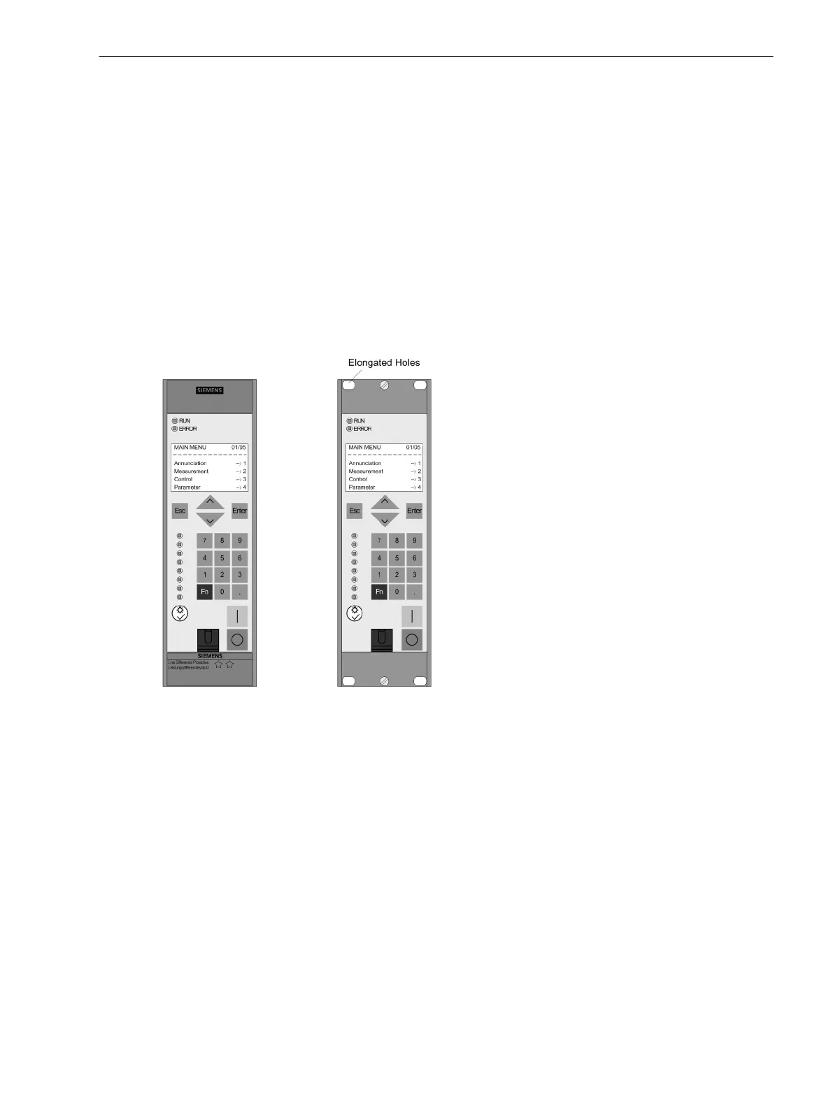
Remove the 2 covers at the top and bottom of the front cover. Thus, 4 elongated holes are revealed in
the mounting bracket and can be accessed.
•
Insert the device into the panel cut-out and fasten it with four screws. For dimensional drawings, refer to
Section 4.19 Dimensions.
•
Mount the 2 covers again.
•
Connect a solid low-ohmic protective and operational ground to the grounding terminal of the device.
The cross-section of the cable used must correspond to the maximum connected cross-section but must
be at least 2.5 mm
2
(Grounding area > M4, grounding area to be lacquer-free).
•
Connections are to be established via the screw terminals on the rear panel of the device in accordance
with the circuit diagram. The details on the connection technique for the communication modules at the
bottom of the device (port A and port B) in accordance with the SIPROTEC 4 System Description and the
details on the connection technique for the current and voltage terminals on the rear of the device in the
Sections “Connections of the Current Terminals” and “Connections of the Voltage Terminals” must be
strictly observed.
[schalttafeleinbau-7sj80-1-6tel-gehaeuse-20070107, 1, en_US]
Figure 3-12 Panel flush mounting of a 7SD80
Cubicle Mounting
To install the device in a rack or cubicle, two mounting brackets are required. The ordering codes are stated in
Appendix, Section A Ordering Information and Accessories.
The housing (housing size
1
/
6
) has 2 covers and 4 fixing holes.
•
Loosely screw the two angle rails into the rack or cubicle with 4 screws each.
•
Remove the 2 covers at the top and bottom of the front cover. Thus, 4 elongated holes are revealed in
the mounting bracket and can be accessed.
•
Secure the device to the angle rails with 4 screws.
•
Mount the 2 covers again.
•
Tighten the 8 screws of the the angle rails in the rack or cubicle.
3.1.3.3
Mounting and Commissioning
3.1 Mounting and Connections
SIPROTEC 4, 7SD80, Manual 219
E50417-G1100-C474-A2, Edition 02.2018

 Loading...


