[7sd80-rs232-110524, 1, --_--]
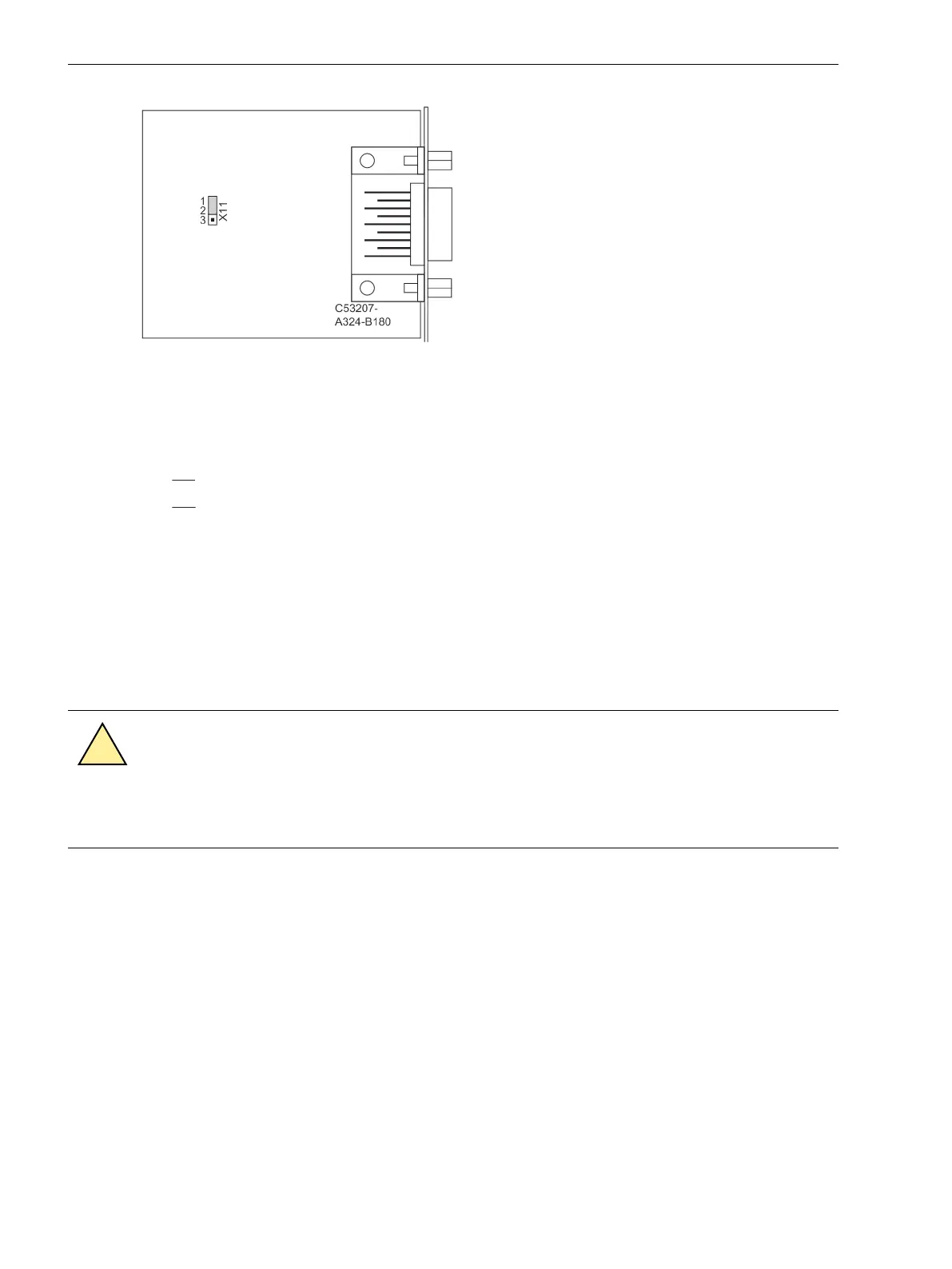
Figure 3-19 Position of jumper X11 on the RS 232 interface
With data cables, the connections are designated according to DIN 66020 and ISO 2110:
•
TxD = Data output
•
RxD = Data input
•
RTS = Request to send
•
CTS = Clear to send
•
GND = Signal/Chassis Ground
The cable shield is to be grounded at both ends. For extremely EMC-prone environments, the GND may be
connected via a separate individually shielded wire pair to improve immunity to interference.
Protection Data Interfaces - Copper
Connect the copper protection data interfaces (electrical) to terminal block D using copper conductors.
Fiber-optic Cables
WARNING
Laser Radiation!
²
Do not look directly into the fiber-optic elements!
Signals transmitted via optical fibers are unaffected by interference. The fibers guarantee electrical isolation
between the connections. Transmit and receive connections are represented by symbols.
The standard setting of the character idle state for the optical fiber interface is “Light off”. If the character idle
state is to be changed, use the operating program DIGSI as described in the SIPROTEC 4 System Description.
Checking the Protection Data Communication
The protection data communication usually goes directly from device to device either via electrical connection
or optical fiber.
3.2.2
Mounting and Commissioning
3.2 Checking Connections
224 SIPROTEC 4, 7SD80, Manual
E50417-G1100-C474-A2, Edition 02.2018

 Loading...


