[dsub-buchsen-20070111, 1, en_US]
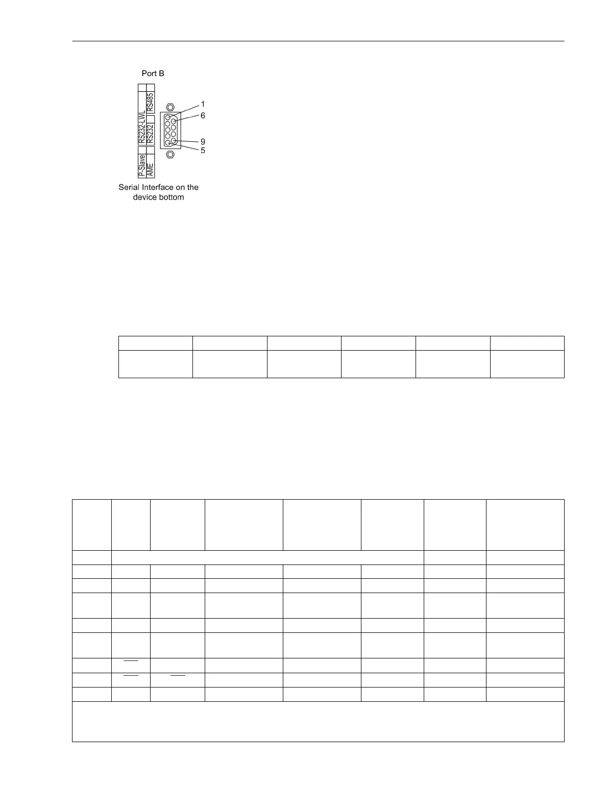
Figure 3-18 Serial interface at the device bottom
USB Interface
The USB interface can be used to establish a connection between the protection device and your PC. For the
communication, the Microsoft Windows USB driver is used which is installed together with DIGSI (as of version
V4.82). The interface is installed as a virtual serial COM port. We recommend the use of standard USB cables
with a maximum length of 5 m/16 ft.
Table 3-2 Assignment of the USB socket
Pin-No. 1 2 3 4 Housing
USB VBUS
(unused)
D- D+ GND Shield
Connections at Port A
Protection data interface optical fiber cable with LC duplex connector.
The order numbers of the exchange modules are listed in the Appendix in Section A Ordering Information and
Accessories, Accessories.
Connections at port B
Table 3-3
Assignments of the port B sockets
Pin-No. RS232 RS232 time
synchroni-
zation
2)
RS485 Profibus DP,
RS485
Modbus
RS485
DNP3.0
RS485
Ethernet
EN 100
IEC 60870–5–
103
redundant
1 Shield (with shield ends electrically connected) Tx+ B/B’ (RxD/TxD-P)
2 RxD – – – – Tx– A/A’ (RxD/TxD-N)
3 TxD – A/A’ (RxD/TxD-N) B/B’ (RxD/TxD-P) A Rx+ –
4 – – – CNTR-A (TTL) RTS (TTL
level)
— –
5 GND GND C/C’ (GND) C/C’ (GND) GND1 — –
6 – – – +5 V ((max. load
<100 mA)
VCC1 Rx– –
7 RTS –
–
1)
– – — –
8 CTS CTS B/B’ (RxD/TxD-P) A/A’ (RxD/TxD-N) B — –
9 – – – – – not available not available
1)
Pin 7 trägt auch bei Betrieb als RS485-Schnittstelle das Signal RTS mit RS232-Pegel. Pin 7 darf deshalb nicht anges-
chlossen werden!
2)
Für Zeitsynchronisation über RS232 ist die Steckbrücke X11 in Stellung 1-2 nötig.
Mounting and Commissioning
3.2 Checking Connections
SIPROTEC 4, 7SD80, Manual 223
E50417-G1100-C474-A2, Edition 02.2018

 Loading...


