secondary circuit, individual or all measuring loops may mistakenly see a voltage of zero. Simultaneously
existing load currents may then cause spurious pickup. When such a measuring voltage failure is detected,
those protection functions are blocked whose measuring principle is based on undervoltage. The definite time
overcurrent protection as emergency function is possible during voltage failure, provided that the time over-
current protection is parameterized accordingly (refer to Section 2.4 Backup overcurrent).
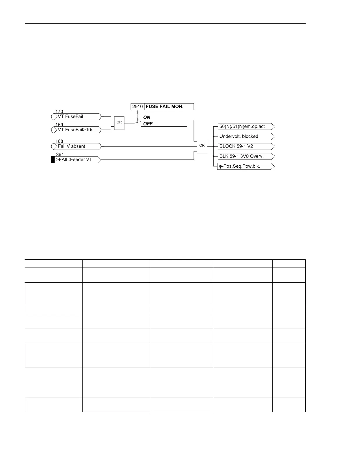
Figure 2-72 shows the effect on protection functions of measuring voltage failure detected by the “Fuse-
Failure-Monitor”
VT FuseFail
(no. 170),
VT FuseFail>10s
(no. 169), additional measuring voltage
failure monitoring
Fail V absent
(no. 168) and binary input of voltage transformer miniature circuit
breaker
>FAIL:Feeder VT
(no. 361).
[lo-7sd80-ffm-mcl-20110316, 1, en_US]
Figure 2-72 Impact of the measuring voltage failure
Fault Responses
Depending on the type of fault detected, an alarm is output, the processor system is restarted or the device is
taken out of operation. After three unsuccessful restart attempts, the device is also shut down. The device
ready relay drops out and indicates the device failure with its NC contact (“life status contact”). The red
“ERROR” LED on the device front lights up, provided that there is an internal auxiliary voltage, and the green
“RUN” LED goes off. If the internal auxiliary voltage supply fails, all LEDs are dark. Table 2-4 shows a summary
of the monitoring functions and the fault responses of the device.
Table 2-4
Summary of the Device's Fault Responses
Monitoring Possible causes Fault response Indication (no.) Output
Auxiliary voltage failure External (aux. voltage)
Internal (converter)
Device out of operation All LEDs dark
DOK
2)
drops
out
Measured-value acquis-
ition
Internal (converter or refer-
ence voltage)
Protection out of opera-
tion, alarm
LED “ERROR”
Error A/D-conv.
(181)
DOK
2)
drops
out
Buffer battery Internal (Buffer battery) Indication
Fail Battery
(177)
as routed
Hardware watchdog Internal (processor failure) Device out of operation LED “ERROR”
DOK
2)
drops
out
Software watchdog Internal (program
sequence)
Restart attempt
1)
LED “ERROR”
DOK
2)
drops
out
Working memory ROM Internal (RAM)
Restart attempt
1)
,
Restart abort
Device out of operation
LED blinkt
DOK
2)
drops
out
Program memory RAM Internal (EPROM)
Restart attempt
1)
LED “ERROR”
DOK
2)
drops
out
Settings memory Internal (Flash-EPROM or
RAM
Restart attempt
1)
LED “ERROR”
DOK
2)
drops
out
Sampling frequency Internal (clock generator)
Restart attempt
1)
LED “ERROR”
DOK
2)
drops
out
2.14.1.4
Functions
2.14 Monitoring Functions
158 SIPROTEC 4, 7SD80, Manual
E50417-G1100-C474-A2, Edition 02.2018

 Loading...


