Effective attenuation < 0.5 dB
Fault attenuation > 20 dB
UL listed No
NOTE
The PROT CU communication interface is protected by a protective circuit (surge arrester) on the primary
side. Therefore, checking the insulation at terminals D1 and D2 is not possible at a later time. Component
testing is performed with AC 70 V. For type tests without protective circuit, voltage immunity is tested with
AC 1.9 kV.
Installation or Replacement of a SIPROTEC 4 Communication Module
The following description assumes the normal case that a SIPROTEC 4 communication module which has not
yet been existing is retrofitted.
If a SIPROTEC 4 communication module has to be removed or replaced, the steps are to be performed in
reverse order.
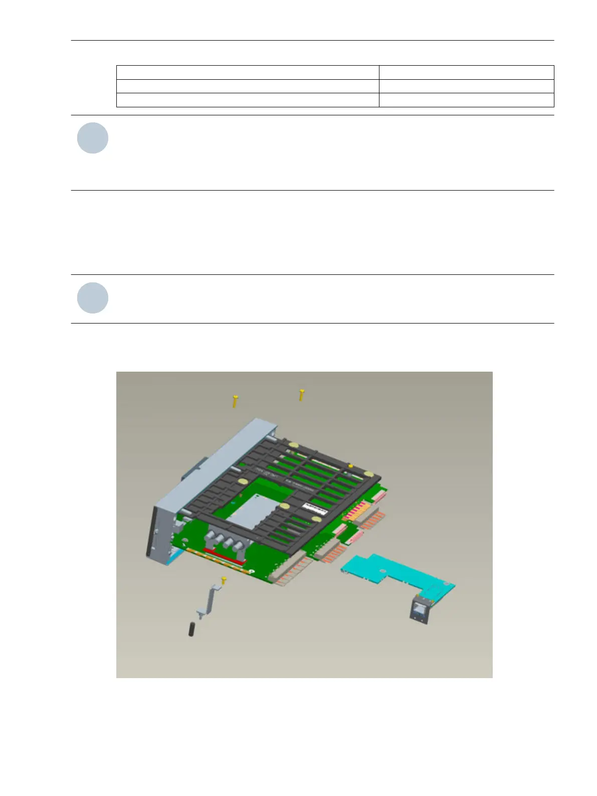
NOTE
Installation is only possible alone or before installing the optical fiber protection interface.
If an optical fiber protection data interface exists, it has to be removed before installing the SIPROTEC 4
communication module. As shown in the following illustration, the parts shown in the lower left section (Z
angle, plastic column) have to be removed to this end. First loosen the three screws for this purpose.
[7sj80-einschub_kpl_02-201201, 1, --_--]
Figure 3-7
Dismounting the FO protection data interface
Mounting and Commissioning
3.1 Mounting and Connections
SIPROTEC 4, 7SD80, Manual 215
E50417-G1100-C474-A2, Edition 02.2018

 Loading...


