[7sj80-einschub_slot, 1, --_--]
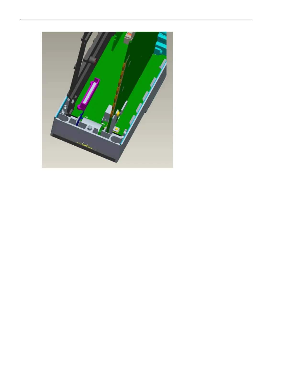
Figure 3-8
7SD80 device with adapter
The SIPROTEC 4 communication module is inserted via the large window in the plastic supporting plate. The
direction of insertion is not arbitrary. The module is held at its mounting bracket. The opposite end of the
module is inserted with the same orientation in the window opening, under the supporting plate and any
existing extension I/O. The module bracket is turned towards the Ethernet module locking latch at the
supporting plate. Thus, even the longest connection elements of the communication module can be moved in
this space between the lower supporting plate reinforcement and the locking latch in the direction of the
transformer module. The mounting bracket of the module is now drawn up to the stop in the direction of the
lower supporting plate reinforcement. Thus, the 60-pin plug connector on the module and the basic I/O board
are aligned on top of each other. The alignment has to be checked via the opening at the bottom of the rack.
Attach the module's mounting rail from the back side of the basic I/O using 2 M 2.5 screws.
Mounting and Commissioning
3.1 Mounting and Connections
216 SIPROTEC 4, 7SD80, Manual
E50417-G1100-C474-A2, Edition 02.2018

 Loading...


