[prinzip-ausloesekrueb-2-be-wlk-010802, 1, en_US]
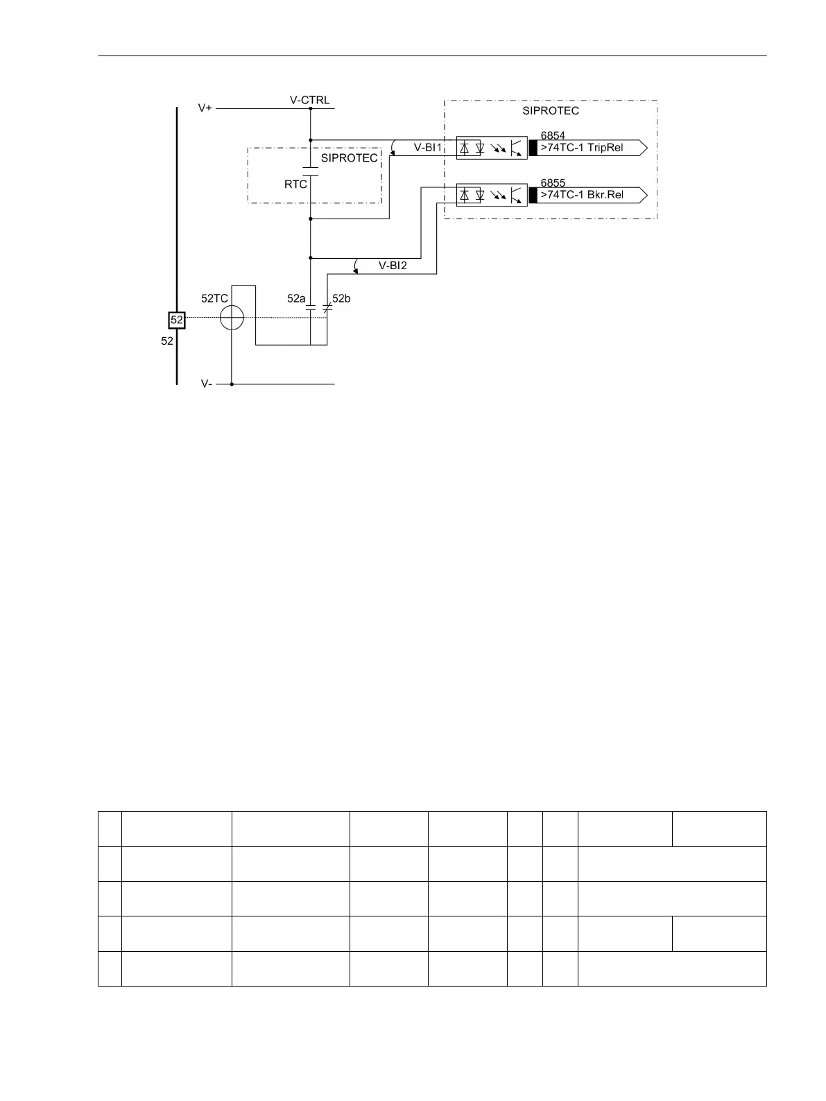
Figure 2-73 Principle of the trip circuit monitoring with two binary inputs
RTC Relay trip contact
52 Circuit breaker
52TC Circuit-breaker trip coil
52a Circuit-breaker auxiliary contact (NO contact)
52b Circuit-breaker auxiliary contact (NC contact)
V-Ctrl Control Voltage (tripping voltage)
V-BI1 Input voltage for first binary input
V-BI2 Input voltage for second binary input
Monitoring with two binary inputs does not only detect interruptions in the trip circuit and loss of control
voltage, it also monitors the response of the circuit breaker using the position of the circuit-breaker auxiliary
contacts.
Depending on the conditions of the trip contact and the circuit breaker, the binary inputs are activated (logical
condition “H” in the following table), or faulted (logical condition “L”).
A state in which both binary inputs are not activated (“L”) is only possible in intact trip circuits for a short tran-
sition period (trip relay contact closed but circuit breaker not yet open).
A continuous state of this condition is only possible when the trip circuit has been interrupted, a fault exists in
the trip circuit, a loss of battery voltage occurs, or malfunctions occur with the circuit-breaker mechanism.
Therefore, it is used as monitoring criterion.
Table 2-5
Condition Table for Binary Inputs, Depending on RTC and CB Position
No
.
Command relay Circuit breaker 52a contact 52b contact BI 1 BI 2 Dynamic state Static state
1 Open EIN Closed Open H L Normal operation with circuit
breaker closed
2 Open AUS Open Closed H H Normal operation with circuit
breaker open
3 Closed EIN Closed Open L L Transition or
disturbance
Disturbance
4 Closed AUS Open Closed L H The command relay has success-
fully activated the circuit breaker
Functions
2.14 Monitoring Functions
SIPROTEC 4, 7SD80, Manual 163
E50417-G1100-C474-A2, Edition 02.2018

 Loading...


