•
Connections are to be established via the screw terminals on the rear panel of the device in accordance
with the circuit diagram. The details on the connection technique for the communication modules at the
bottom of the device (port A and port B) in accordance with the SIPROTEC 4 System Description and the
details on the connection technique for the current and voltage terminals on the rear of the device in the
Sections “Connections of the Current Terminals” and “Connections of the Voltage Terminals” must be
strictly observed.
•
Insert the device into the mounting frame (make sure that no cables are jammed).
•
Secure the device to the mounting frame with 4 screws. For dimensional drawings, refer to the Technical
Data, Section 4.19 Dimensions.
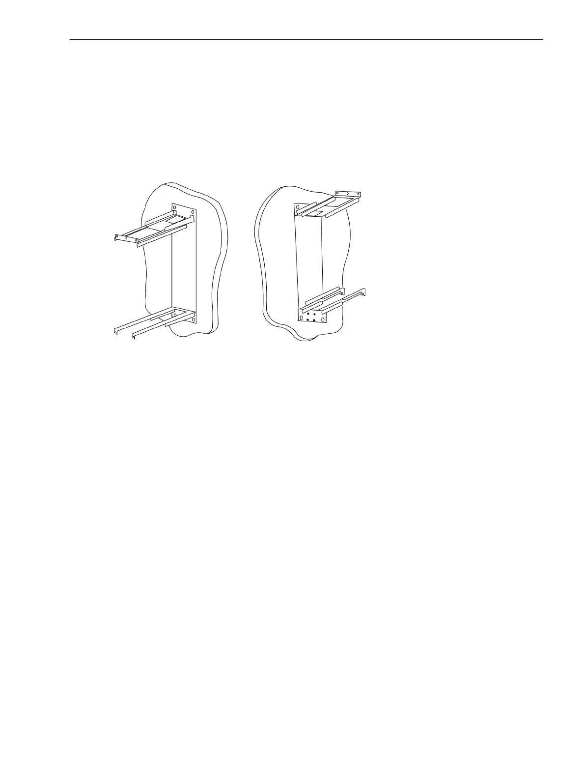
[montagehalterung-20070116, 1, en_US]
Figure 3-14 Mounting rails for panel surface mounting
Mounting and Commissioning
3.1 Mounting and Connections
SIPROTEC 4, 7SD80, Manual 221
E50417-G1100-C474-A2, Edition 02.2018

 Loading...


