[dw_example_temp_sensor_2phase, 2, en_US]
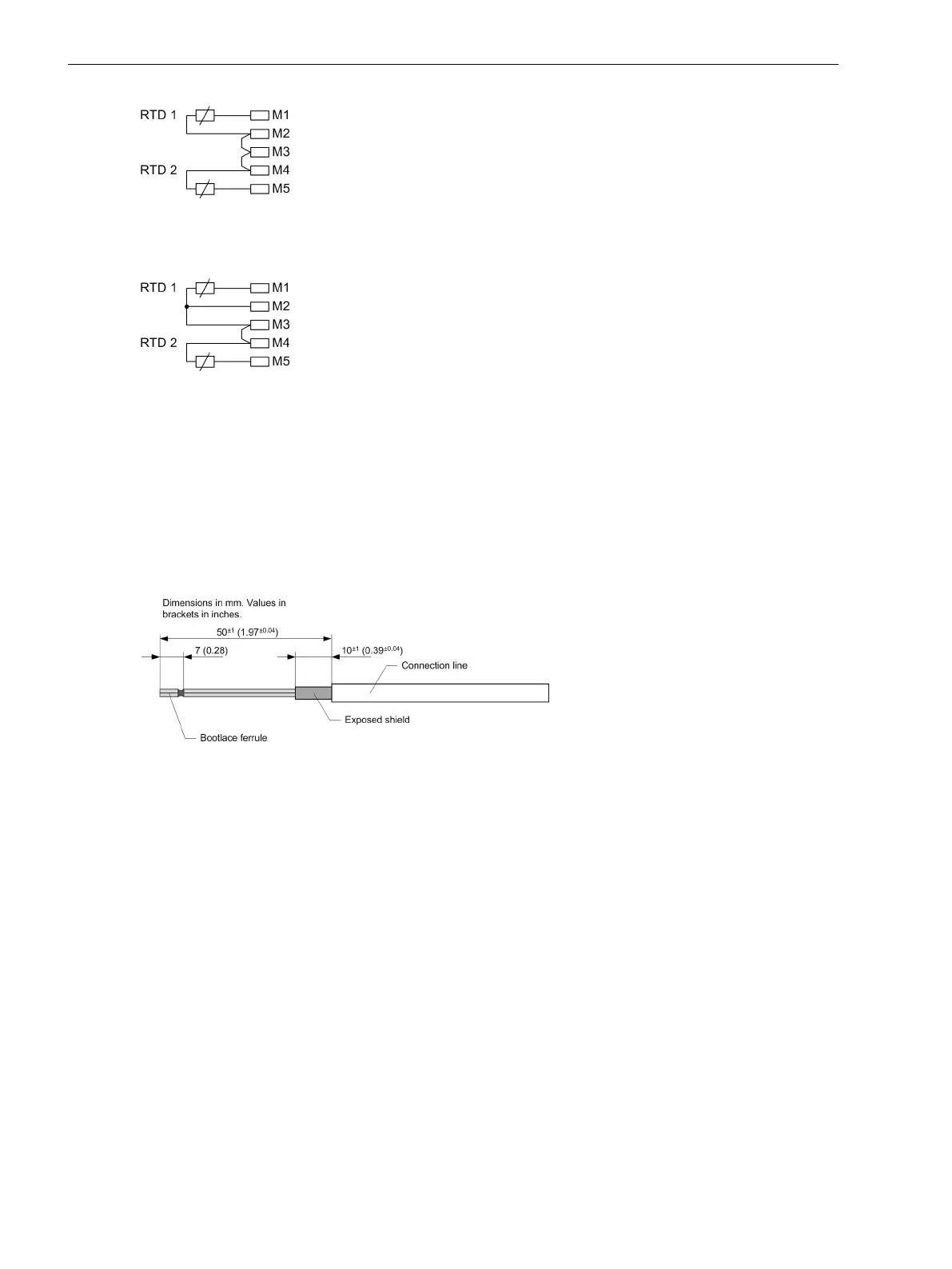
Figure 3-95 Example: Connecting Temperature Sensors RTD 1 (2-Line Terminal) and RTD 2 (2-Line
Terminal) to Terminals M1 to M5
[dw_temperature_sensor, 2, en_US]
Figure 3-96 Example: Connecting Temperature Sensors RTD 1 (3-Line Terminal) and RTD 2 (2-Line
Terminal) to Terminals M1 to M5
Connecting the Lines
When connecting the lines, proceed as follows:
²
Use shielded lines with shielding braid (3-core AWG 24).
²
Prepare the cable as shown in the following figure.
The dimensions in the drawing are designed so that the plug can still be plugged in with the shielding
plate screwed on.
[dw_shielded_line, 1, en_US]
Figure 3-97 Preparing the Cable
²
Connect the lines with bootlace ferrules.
²
Use the included clamps and cable ties to make contact with the cable shield and provide strain relief on
the cable.
Electronic Modules
3.4 Input and Output Modules of Non-Modular Devices (7xx81, 7xx82)
144 SIPROTEC 5, Hardware Description, Manual
C53000-G5040-C002-J, Edition 08.2020

 Loading...


