[dwkl2pol-030211-01.tif, 1, --_--]
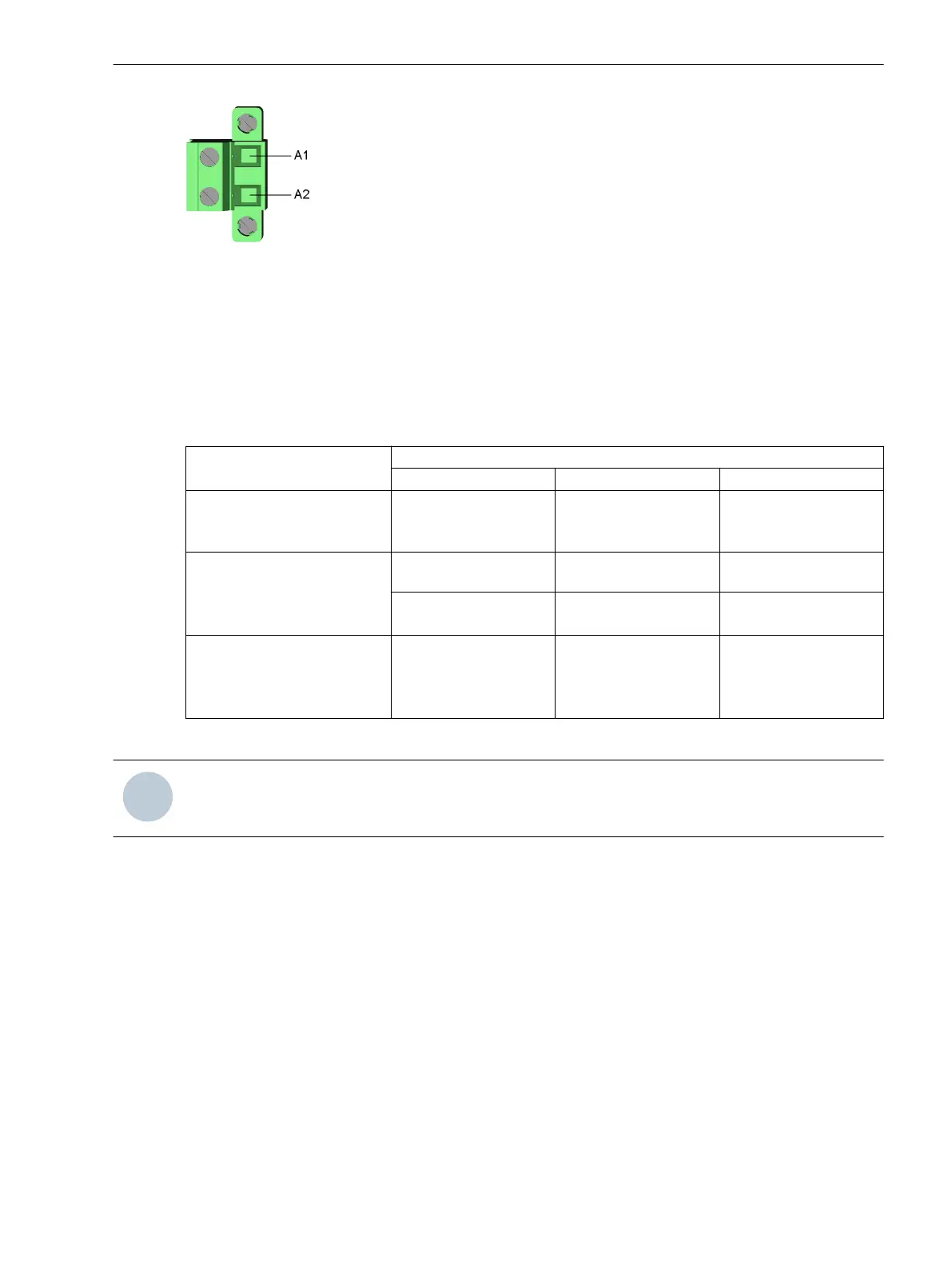
Figure 3-14 Connection of External Power Supply
Plug-In Module Assembly with Integrated Power Supply CB202
Description
The plug-in module assembly CB202 is a PCB assembly with an internal power supply. The plug-in module
assembly CB202 is used in an expansion module. 3 plug-in module positions (M, N and P) are available for
installation of plug-in modules. The plug-in modules can be installed in the following arrangements:
Plug-In Module Position
M N P
Configured with
3 measuring-transducer
modules
Measuring-transducer
module
Measuring-transducer
module
Measuring-transducer
module
Configured with
2 measuring-transducer
modules and
1 communication module
Measuring-transducer
module
Measuring-transducer
module
Communication module
Measuring-transducer
module
Communication module Measuring-transducer
module
Configured with
1 measuring-transducer
module and
2 communication modules
Measuring-transducer
module
Communication module Communication module
Combinations that do not occupy all plug-in module positions are also possible.
NOTE
A communication module cannot be plugged into the plug-in module position M.
The CB202 plug-in module assembly communicates with the base module using a communication connection.
This communication connection is established with a special connecting cable. This connecting cable
(CAT5 FTP patch cable) is always included in the scope of delivery of the CB202 plug-in module assembly and
need not be ordered separately.
The following 2 variants are available for the rated voltage range:
•
DC 24 V to 48 V
•
DC 60 V to 250 V and AC 100 V to 230 V (50 Hz and 60 Hz)
The CB202 plug-in module assembly can be used in the 1st and 2nd device rows.
LEDs of the RJ45 Terminals
The light-emitting diodes (LEDs) signal the operating state of the communication connection. The operating
states are explained in the following table.
3.1.5
3.1.5.1
Electronic Modules
3.1 Power-Supply Modules of the Modular Devices
SIPROTEC 5, Hardware Description, Manual 61
C53000-G5040-C002-J, Edition 08.2020

 Loading...


