[sc_ shielding_plate _mounting-cutout, 1, --_--]
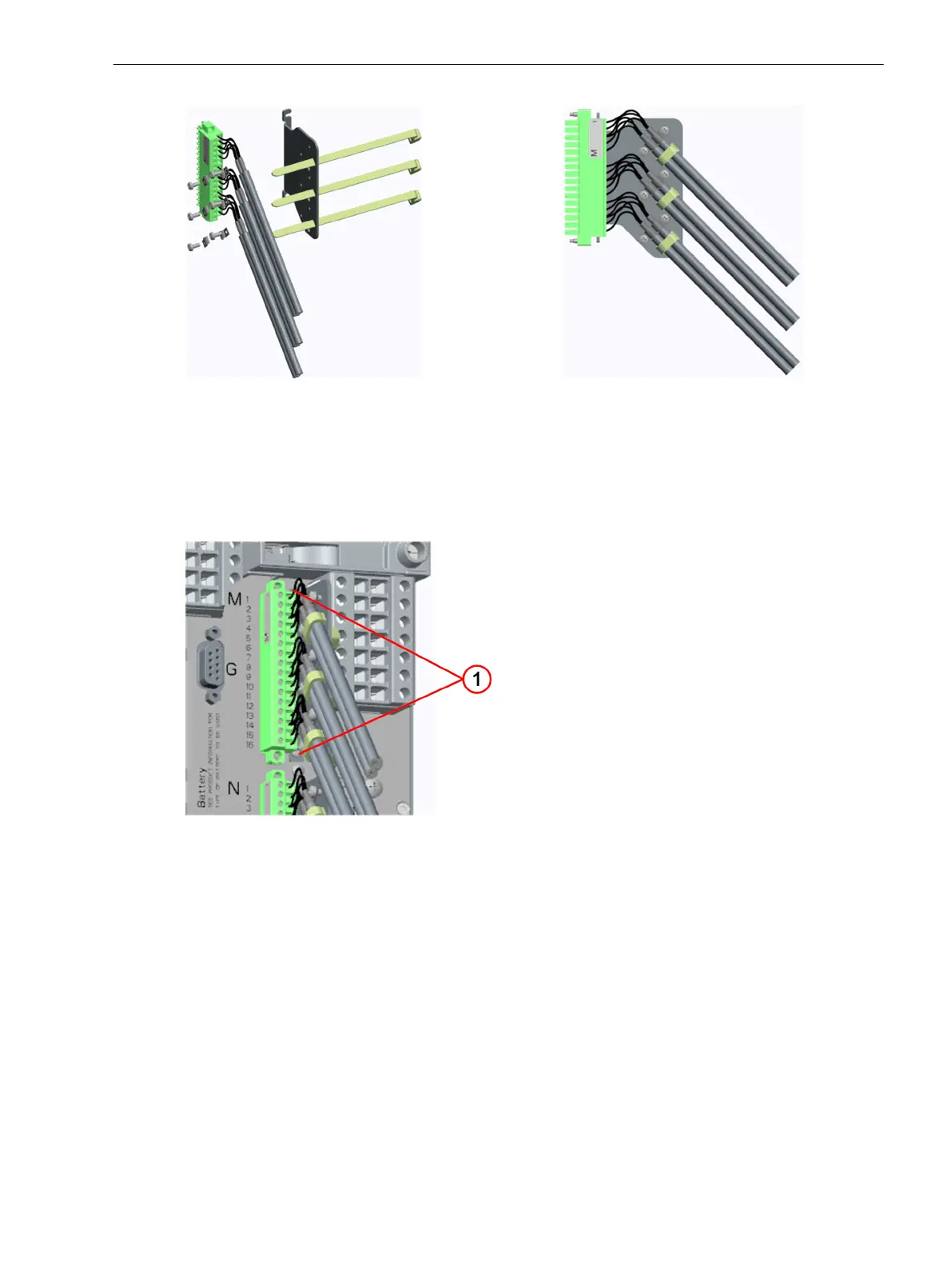
Figure 3-98 Using Clips and Cable Ties
²
Loosen the 2 screws for fastening the shielding plates on the device next to the 16-pole or 17-pole plug
so that there is somewhat more than 2 mm (0.08 in) space.
²
Push the prepared shielding plate under the screw heads and tighten them.
²
Plug in the plug and secure it with its 2 outer screws.
[le_ shielding_plate _screw fastening, 1, --_--]
Figure 3-99 Fastening with Screws
(1) Fastening screws for shielding plate
²
Repeat the steps for the 2nd plug.
Input and Output Module IO112
Description
The terminals for the following are located on the input and output module IO112:
•
5 binary inputs
•
2 binary outputs, of which:
– 2 standard-make contacts (type S)
3.4.7
3.4.7.1
Electronic Modules
3.4 Input and Output Modules of Non-Modular Devices (7xx81, 7xx82)
SIPROTEC 5, Hardware Description, Manual 145
C53000-G5040-C002-J, Edition 08.2020

 Loading...


