[tdio112x, 1, en_US]
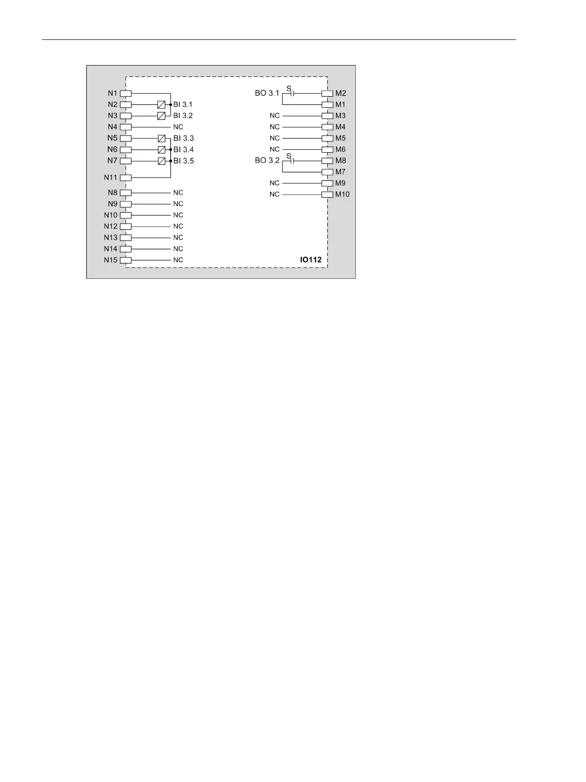
Figure 3-101 IO112 – Connection Diagram
Input and Output Module IO113
Description
The terminals for the following are located on the input and output module IO113:
•
7 binary inputs
•
5 binary outputs, of which:
– 5 standard make contacts (type S)
The connections are distributed over:
•
1 x 10-pole terminal
•
1 x 15-pole terminal
Terminals
Overview of Terminals
The overview of terminals is identical to the module IO110, see Figure 3-88.
3.4.8
3.4.8.1
3.4.8.2
Electronic Modules
3.4 Input and Output Modules of Non-Modular Devices (7xx81, 7xx82)
148 SIPROTEC 5, Hardware Description, Manual
C53000-G5040-C002-J, Edition 08.2020

 Loading...


