²
Extend the device configuration in DIGSI and load it to the device.
²
Resume operation of the device.
Surface-Mounted Devices with Detached On-Site Operation Panel
Basic Rules for Expansion
NOTE
Prepare the following tools for the device expansion:
•
Phillips screwdriver size PZ1 and PZ2
•
Screwdriver DIN 4 x 0.8
•
During assembly, use the prescribed torques (see chapter 6.13 Design Data).
Comply with the following basic rules when expanding devices:
•
Always fit the base module on the right in the 1st device row.
•
Always fit the expansion modules from right to left.
•
Always fit the on-site operation panel of the base module on the left.
•
Always fit the on-site operation panels of the expansion modules from left to right.
•
Always install a power-supply module PS203 on the right as the first unit in the 2nd device row.
•
Note that the PS203 must always have the same rated voltage as the base module.
•
Always mount the redundant PS204 power-supply module at the position at the very left in the corre-
sponding row (seen from the front). If a CB202 PCB assembly is used in the row, this CB202 PCB assembly
must always be plugged on the left of the power-supply module PS204 (at the very left). You can find an
example in chapter 3.1.4.2 Positioning Specifications.
•
Note that the power-supply module PS204 must always have the same rated voltage as the base module.
•
The distance between the device and the on-site operation panel is limited to not more than 5 m
(196.85 in) by the length of the connecting cable.
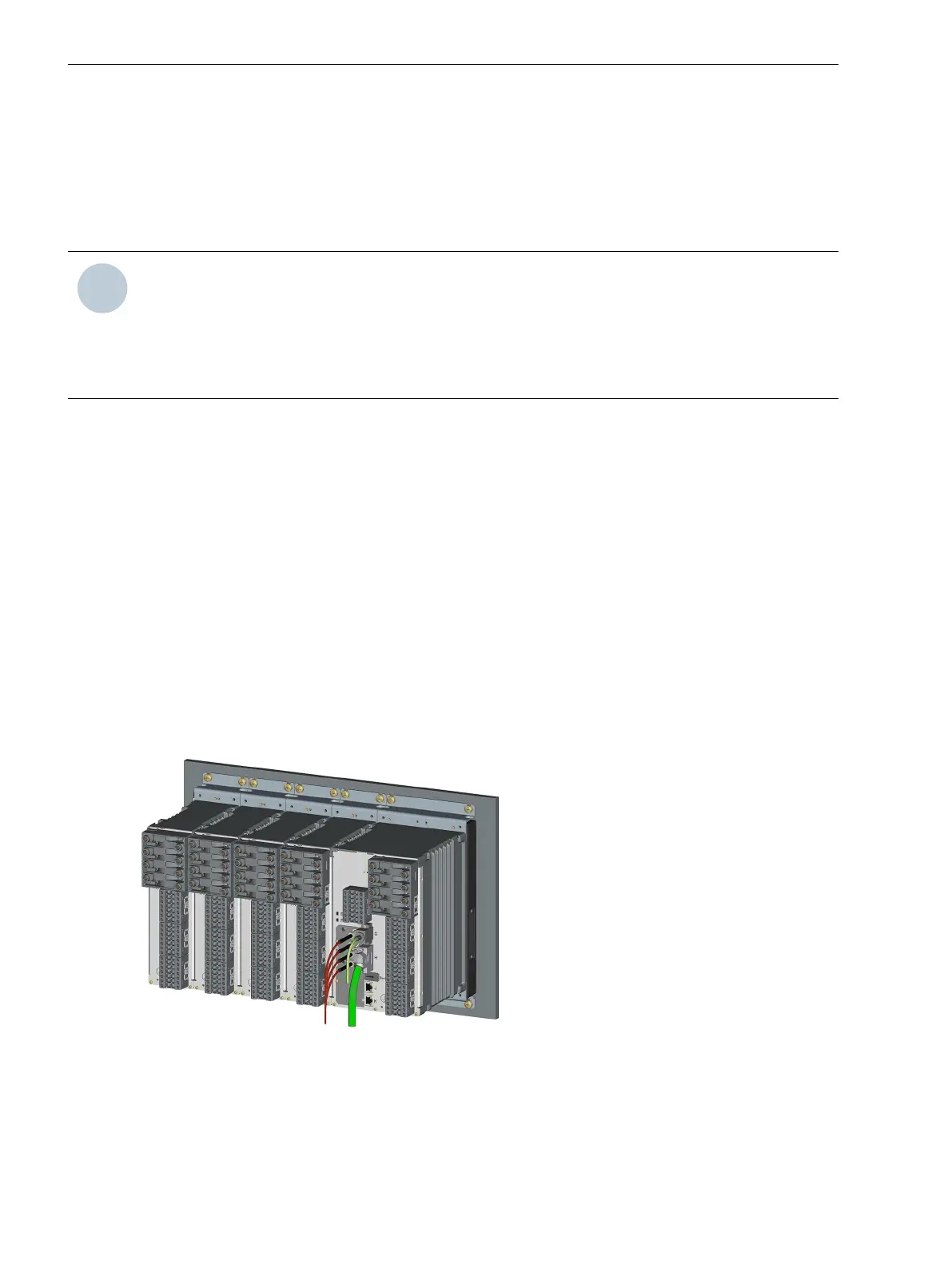
[dwauizei-040211-01.tif, 1, --_--]
Figure 5-9 Device Row
5.2.3
5.2.3.1
Working on the Device
5.2 Expanding Modular Devices
192 SIPROTEC 5, Hardware Description, Manual
C53000-G5040-C002-J, Edition 08.2020

 Loading...


