[td_io240x, 1, en_US]
Figure 3-70
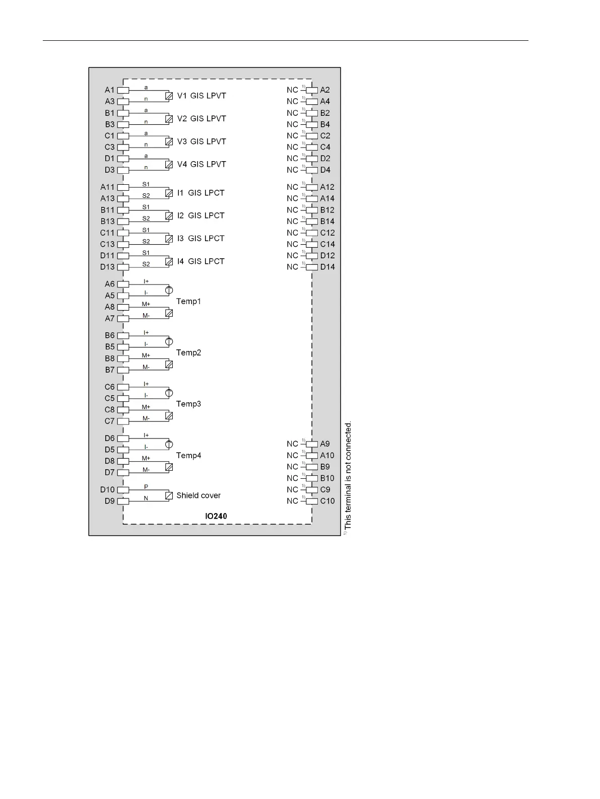
IO240 – Connection Diagram
Connections of Temperature Sensors
When connecting the Siemens high-voltage LPIT GIS sensors to the LPIT module IO240, proceed as follows:
²
Use the delivered cable LEONI L45551-P42-B5 and confection the cable as explained in the user manual
of the LPIT GIS sensor.
The L45551-P42-B5 cable has 4 twisted pairs: 1 pair for the low-power voltages, 1 pair for the low-power
currents, and 2 pairs for the PT100 temperature sensor connection.
²
Connect the signal cables to the corresponding terminals, refer to Figure 3-69.
²
Connect the shields with the 4-mm cable ring-type lugs to the marked M4 screw with 1.6-Nm torque at
the rear plate of the LPIT module IO240.
3.2.20.3
Electronic Modules
3.2 Input and Output Modules of the Modular Devices
118 SIPROTEC 5, Hardware Description, Manual
C53000-G5040-C002-J, Edition 08.2020

 Loading...


