[dwrj45pb-030211-01.tif, 1, en_US]
Figure 4-4 RJ45 Terminals for the Serial Signals of the RS485 Interface
Cabling Examples of Devices with Serial Electrical Modules
Serial electrical RS485 connections of devices in the SIPROTEC 5 series can be cabled with low-cost Ethernet
patch cables. Special bus cables and adaptors are not needed. Pay attention to the following note if you
include devices from the SIPROTEC 4 series in the connection.
NOTE
The RS485 interface in devices of the SIPROTEC 4 series is a D-Sub 9 connection with a connected terminal
resistor.
If you connect devices from the SIPROTEC 5 series with devices from the SIPROTEC 4 series, then use a Y
adaptor with the order designation 7XV5103-2BA00. Complete the connection on the last device with a
terminal resistor. For the SIPROTEC 5 device, use a terminal resistor with the order designation RS485-
Terminator 7XV5103-5BA00.
[dwserma1-030211-04.tif, 1, en_US]
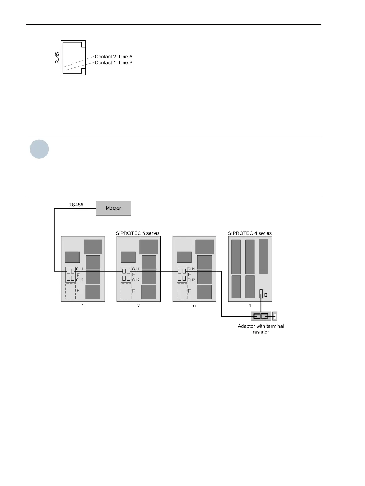
Figure 4-5 Communication with a Single Master Using an RS485 Bus
The preceding figure shows the cabling using the new RJ45 sockets in a simplified format. The serial RS485
bus can be extended by simply connecting Ethernet patch cables from device to device.
Plug-In Modules
4.2 Communication Modules
160 SIPROTEC 5, Hardware Description, Manual
C53000-G5040-C002-J, Edition 08.2020

 Loading...


