•
Always fit the on-site operation panels of the expansion modules from left to right.
•
Always fit the on-site operation panel of the expansion module with the key switches in the 1st place
next to the on-site operation panel of the base module.
•
Always fit the on-site operation panels without LEDs last.
•
Join the on-site operation panels to one another with 2 mounting brackets.
•
Always install a power-supply module PS203 on the right as the first unit in the 2nd device row.
•
Note that the PS203 must always have the same rated voltage as the base module.
•
Always mount the redundant power-supply module PS204 at the very right in the corresponding row
(seen from the front). If a CB202 PCB assembly is used in the row, this CB202 PCB assembly must always
be plugged on the right of the power-supply module PS204 (at the very right). You can find an example
for this in chapter 3.1.4.2 Positioning Specifications.
•
Note that the power-supply module PS204 must always have the same rated voltage as the base module.
•
In the 2nd device row, you do not need any on-site operation panels, mounting brackets, or distance
frames.
NOTE
When expanding a device in the 1st device row, order 2 mounting brackets that match the width of the
expanded device.
[dwauize1-040211-01.tif, 2, --_--]
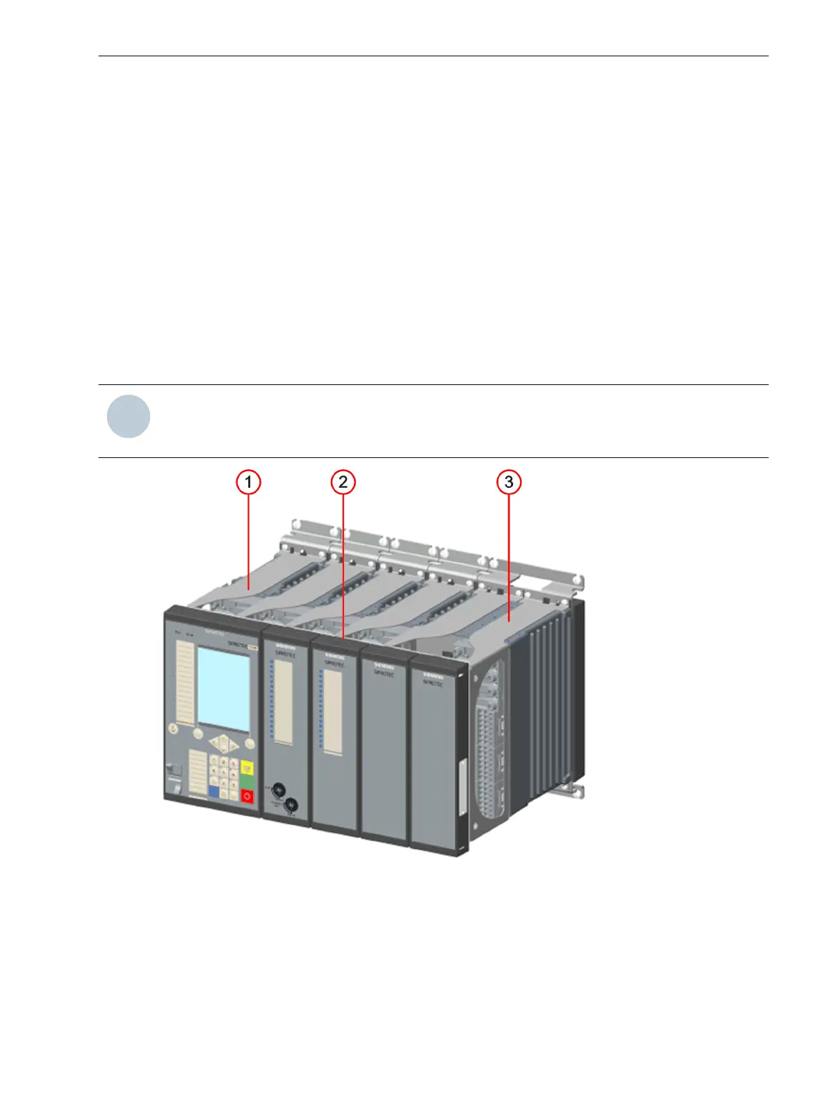
Figure 5-5
Device Row
(1) Distance frame
(2) Mounting bracket
(3)
Distance frame on base module rotated by 180
o
Working on the Device
5.2 Expanding Modular Devices
SIPROTEC 5, Hardware Description, Manual 187
C53000-G5040-C002-J, Edition 08.2020

 Loading...


