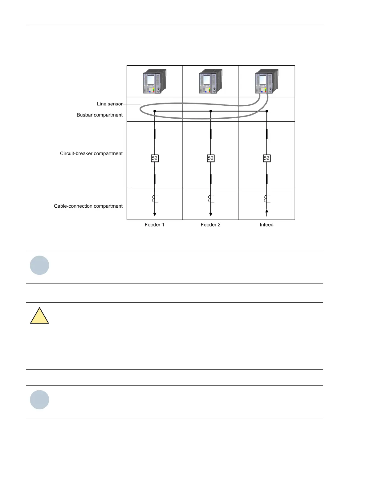
Depending on the possibilities of implementing this in the control cabinet, the line sensor can also be passed
through the circuit-breaker compartment and the cable connection compartment of the feeders in addition to
the busbar compartment.
[dw_Liniensensor, 1, en_US]
Figure 5-16
Laying a Line Sensor Along the Busbar
NOTE
Install the arc sensors in the control cabinet in such a way that the relevant sections are not hidden behind
other system components!
Preparing Installation
CAUTION
Exercise caution with laser beams of the optical plug-in modules.
Noncompliance with the safety notes can result in medium-severe or slight injuries.
²
Do not look directly into the fiber-optic terminals of the active optical plug-in modules, not even with
optical devices. The laser beams can damage the eyes.
²
De-energize the device.
NOTE
Laser class 1 is maintained in compliance with EN 60825-1 and EN 60825-2 when using 1 mm polymer
optical fibers.
²
You need 2 holes (10.0 mm in diameter) in the control cabinet for fastening. Siemens recommends a
distance of approx. 10 cm.
Working on the Device
5.4 Arc Sensors for Module: ARC-CD-3FO
204 SIPROTEC 5, Hardware Description, Manual
C53000-G5040-C002-J, Edition 08.2020

 Loading...


