Power-Supply Module of Non-Modular Devices (7xx81, 7xx82)
Power-Supply Module PS101
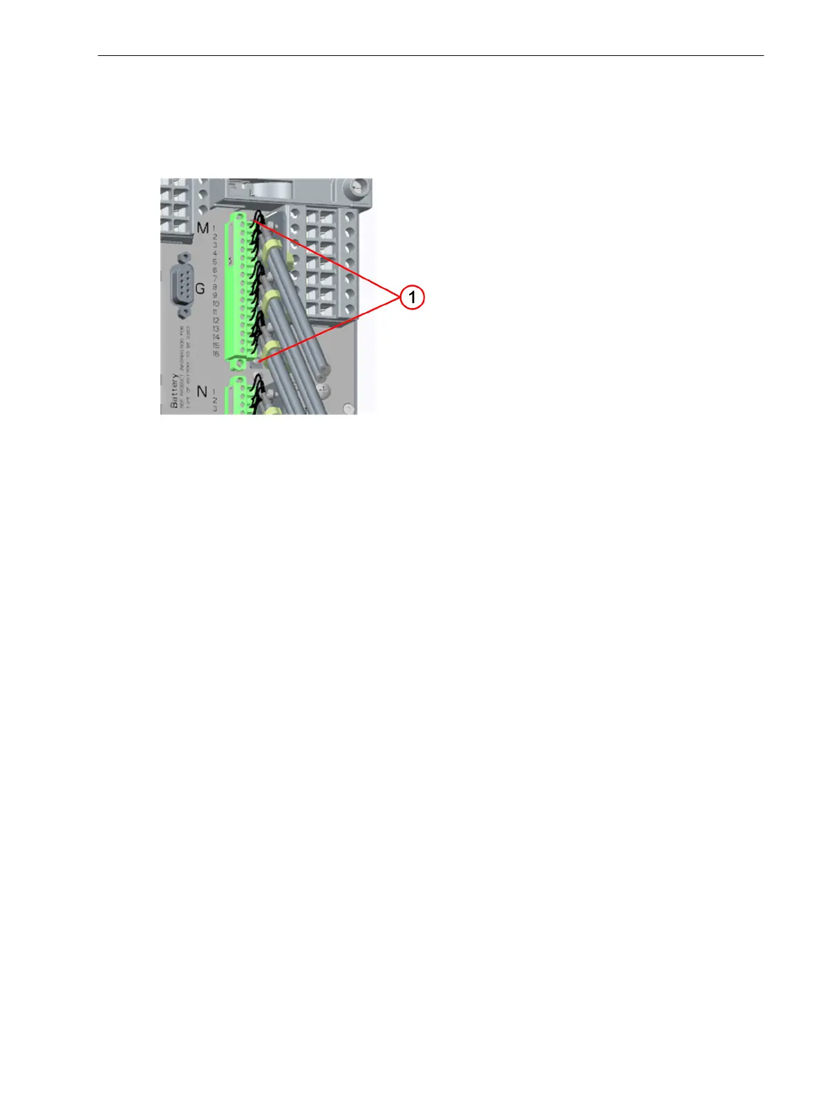
Description
The power-supply module PS101 is always permanently installed in the 1/3 module. The following can be
found on the PS101 module:
•
2 positions for plug-in modules (communication modules, measuring-transducer modules)
•
Terminals for time synchronization and an integrated Ethernet interface
•
A 14-pole voltage terminal (3 binary inputs, 3 binary outputs and connection for power supply)
•
Battery for the CPU
The following 3 variants are available for the rated voltage range:
•
DC 24 V to 48 V
•
DC 60 V to 125 V
•
DC 110 V to DC 250 V and AC 100 V to AC 230 V (50 Hz and 60 Hz)
3.3
3.3.1
3.3.1.1
Electronic Modules
3.3 Power-Supply Module of Non-Modular Devices (7xx81, 7xx82)
SIPROTEC 5, Hardware Description, Manual 125
C53000-G5040-C002-N, Edition 04.2022

 Loading...


