Terminals
Overview of Terminals
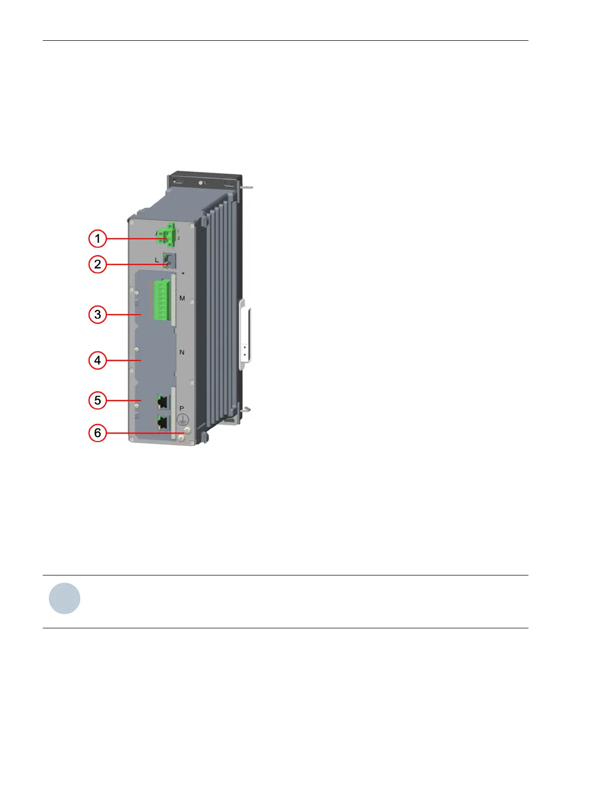
The terminals assigned to the module are identified by the frame in the figure.
[le_io101, 2, --_--]
Figure 3-80
IO101 – Terminals
(1) Current terminal A
(2) Voltage terminal B
(3) Voltage terminal D
(4) Protective grounding terminals
3.4.2.2
Electronic Modules
3.4 Input and Output Modules of Non-Modular Devices (7xx81, 7xx82)
130 SIPROTEC 5, Hardware Description, Manual
C53000-G5040-C002-N, Edition 04.2022

 Loading...


