[le_surface_mounting_front_7SJ81, 1, --_--]
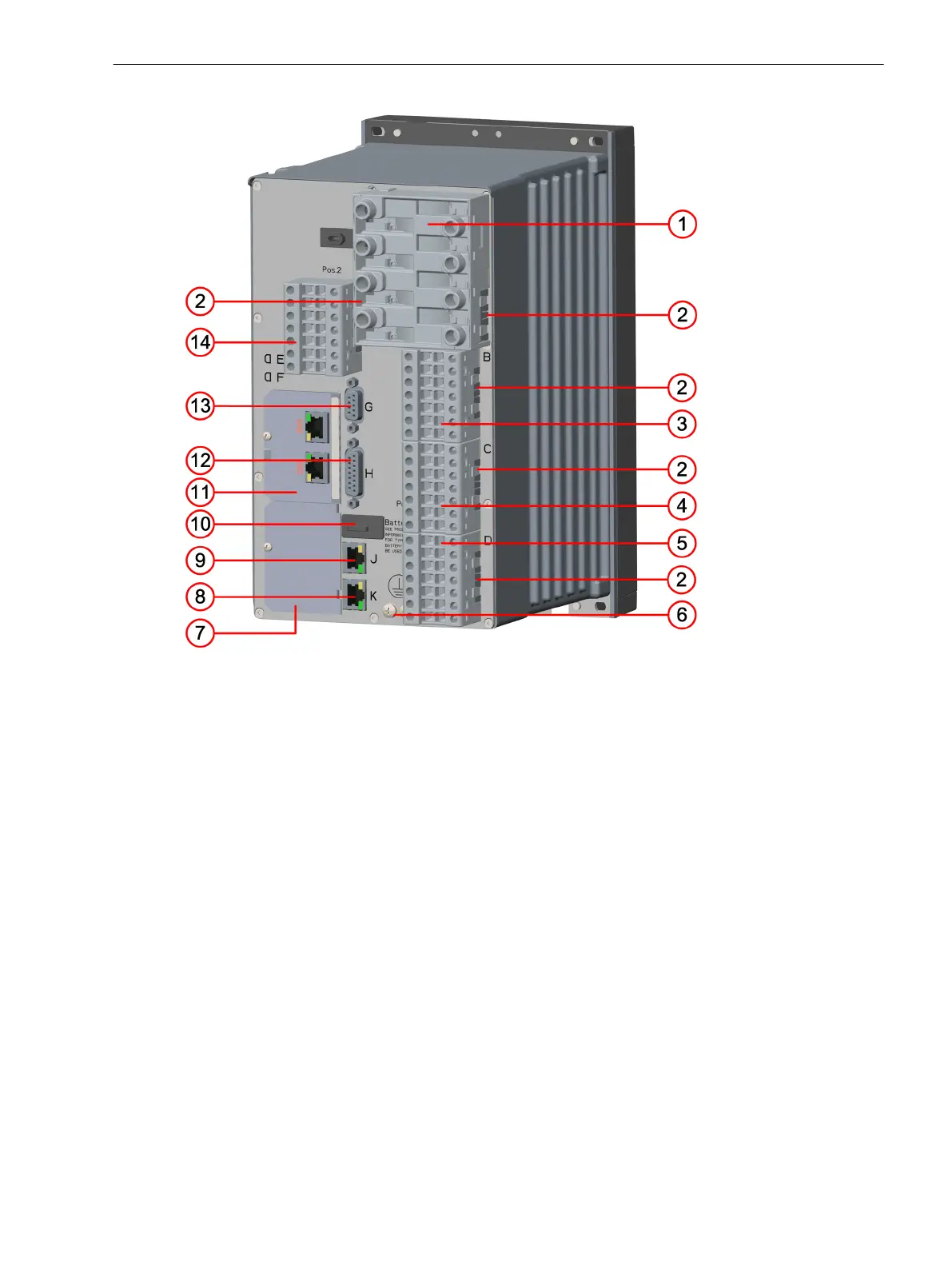
Figure 2-2
Front View – 7xx81
(1) USB connection, type B
(2) On-site operation panel
(3) Bus terminal for expansion module, only possible for modular devices
(4) Keypad without function keys
Forms of Devices and On-Site Operation Panels
2.1 Flush-Mounting Devices
SIPROTEC 5, Hardware Description, Manual 21
C53000-G5040-C002-N, Edition 04.2022

 Loading...


