[le_rear modular device, 3, --_--]
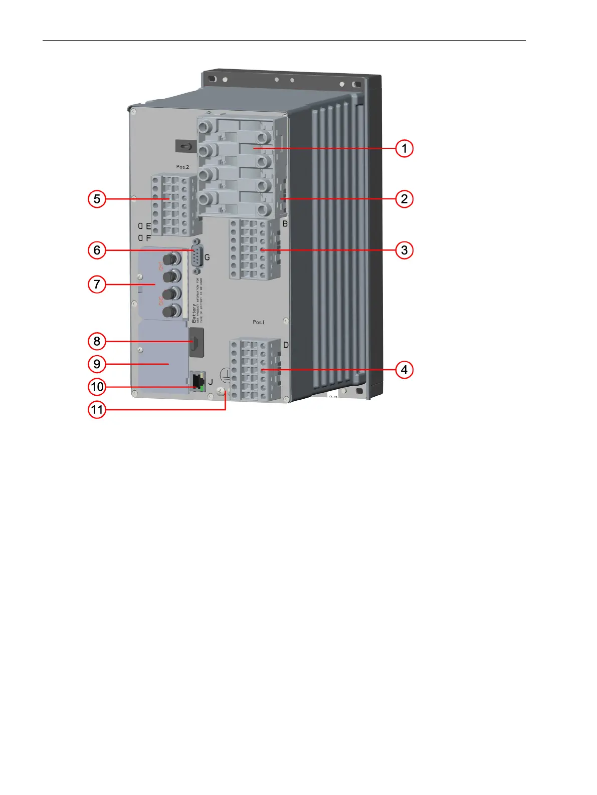
Figure 2-3
Rear View of a Modular Device, Terminals of a Typical Device with IO202
(1) Current terminal 1A
(2) Spring clip
(3) Voltage terminal 1B
(4) Voltage terminal 1C
(5) Voltage terminal 1D
(6) Protective grounding terminals
(7) Plug-in module position F
(8) Terminal for COM link K
(9) Terminal for integrated Ethernet interface J
(10) Battery compartment
(11) Plug-in module position E
(12) Terminal for detached on-site operation panel H
(13) Terminal for time synchronization G
(14) Voltage terminal 2B
(15) For module fastening inside the device, no user function (existence depending on the device
version)
Forms of Devices and On-Site Operation Panels
2.1 Flush-Mounting Devices
22 SIPROTEC 5, Hardware Description, Manual
C53000-G5040-C002-N, Edition 04.2022

 Loading...


