Expansion Module
[le_front expansion module, 1, --_--]
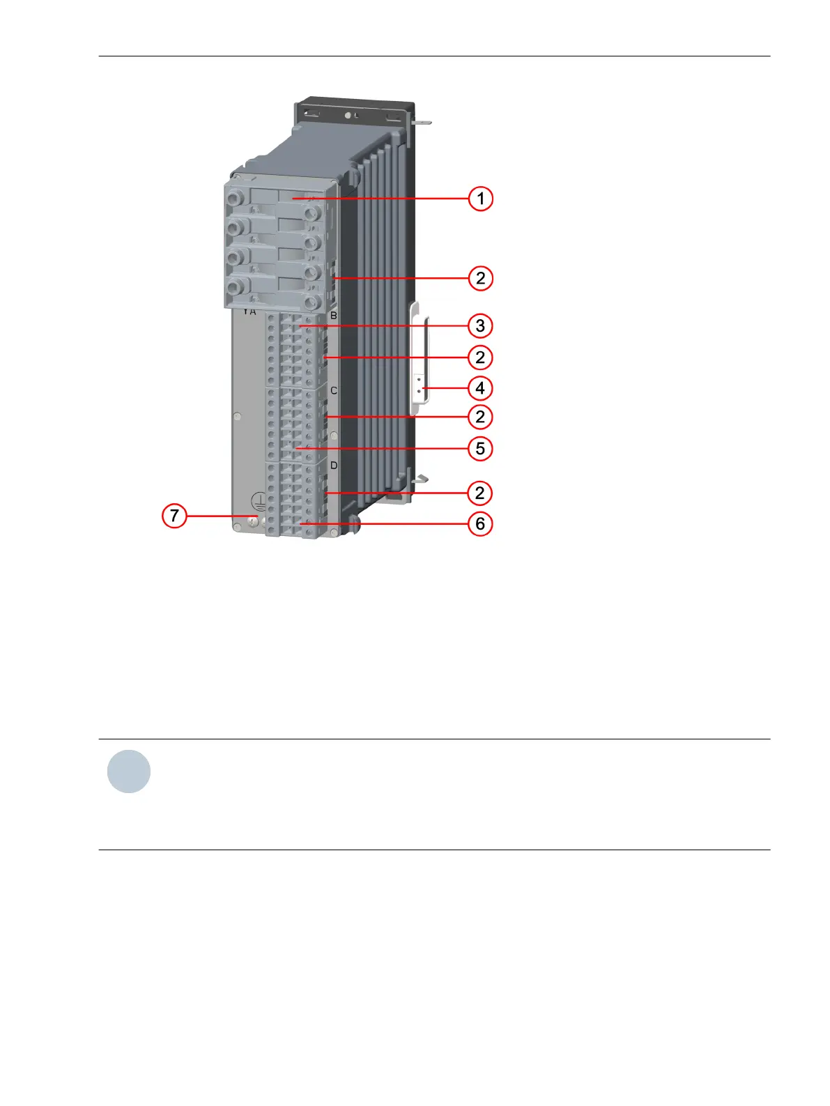
Figure 2-7
Front View of the Expansion Module
(1) Device housing
(2) On-site operation panel
(3) Bus terminal for an additional expansion module (shown with bus termination plate)
Unused bus terminals are sealed with a cover.
Forms of Devices and On-Site Operation Panels
2.1 Flush-Mounting Devices
SIPROTEC 5, Hardware Description, Manual 25
C53000-G5040-C002-N, Edition 04.2022

 Loading...


