Counting Method for Modules in 19-Inch Rack (View of the Rear of the Device)
[dwbgrpos-170713-01.tif, 3, en_US]
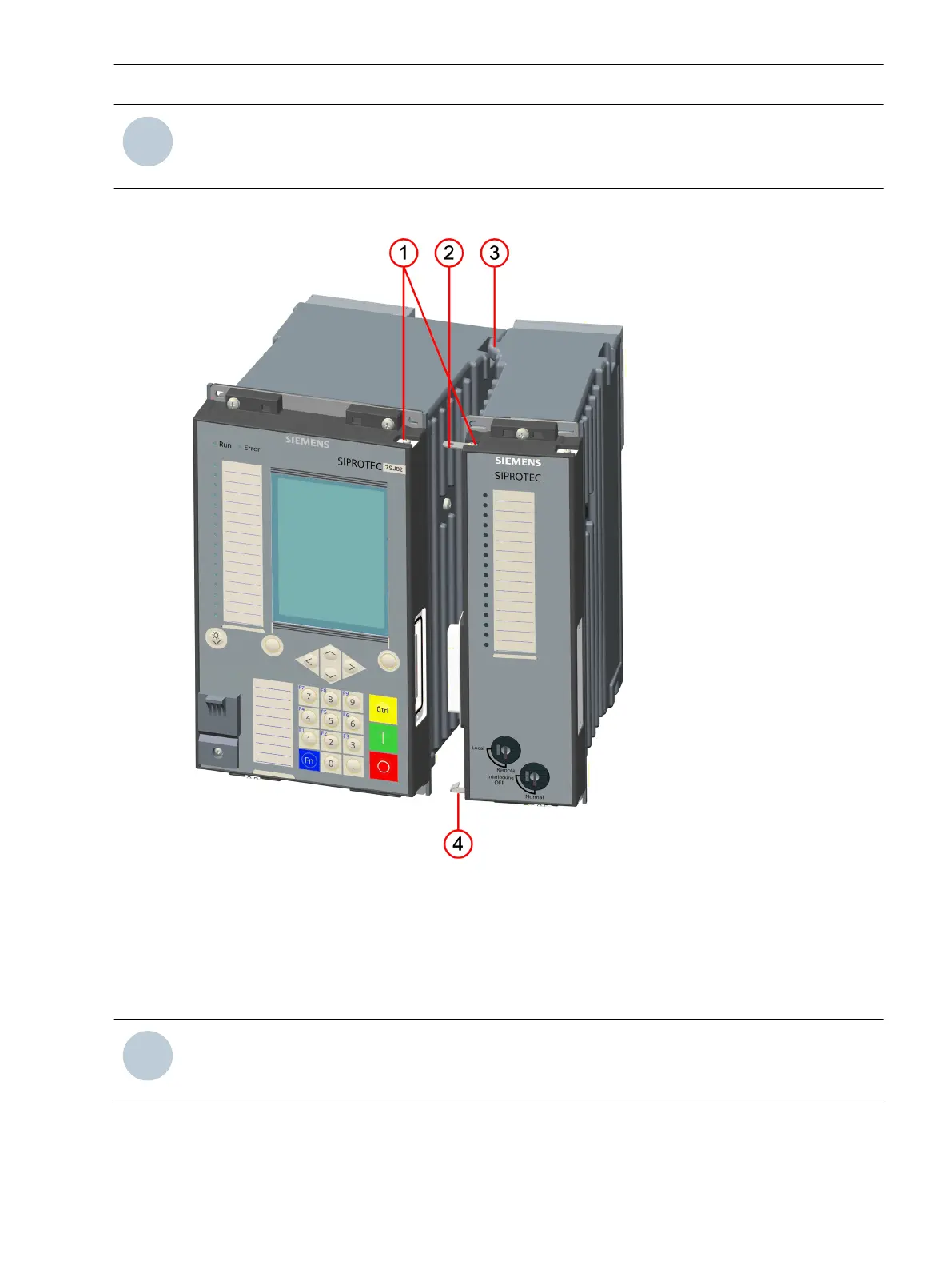
Figure 2-9
Counting Method for Modules in 19-Inch Rack (Example)
(1) Current terminal A
(2) Voltage terminal A, B, C, D
(3) Terminal for time synchronization G
(4) Plug-in module E, F
(5) Terminal for detached on-site operation panel H
(6) Battery compartment
(7) Terminal for integrated Ethernet interface J
(8) Terminal for COM link K
(9) 2-pole terminal to connect power supply
(10) Base module 1/3 of 19 in
(11) Expansion module 1/6 of 19 in
(12) Connecting cable between 1st and 2nd device row
Forms of Devices and On-Site Operation Panels
2.1 Flush-Mounting Devices
SIPROTEC 5, Hardware Description, Manual 27
C53000-G5040-C002-N, Edition 04.2022

 Loading...


