2.14 Thermal Overload Protection
195
7SD610 Manual
C53000-G1176-C145-4
The overload protection can be blocked via a binary input. In doing so, the thermal
images are also reset to zero.
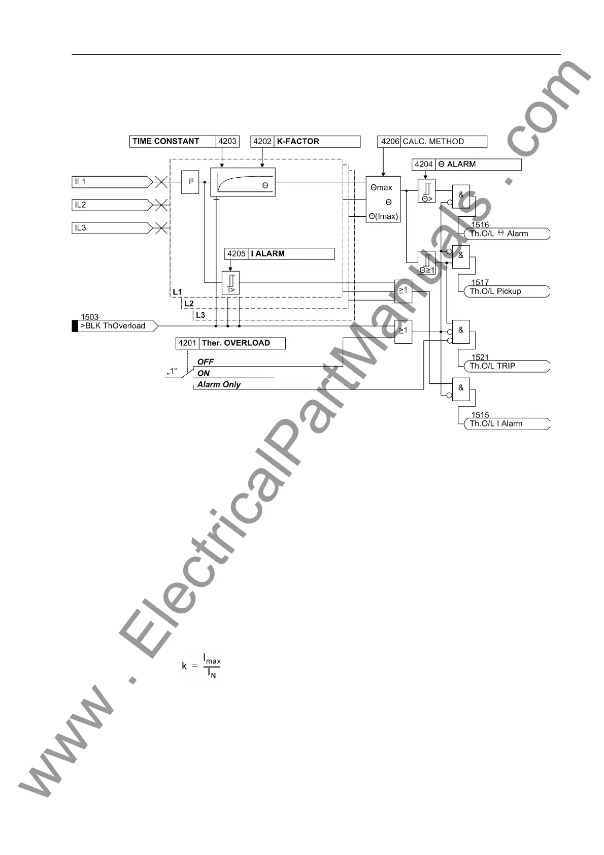
Figure 2-79 Logic diagram of the thermal overload protection
2.14.2 Setting Notes
General A prerequisite for using the thermal overload protection is that during the configuration
of the scope of functions at address 142 Therm.Overload = Enabled was applied.
At address 4201 Ther. OVERLOAD the function can be turned ON or OFF. Further-
more, Alarm Only can be set. With the latter setting the protective function is active
but only outputs the indication „Th.O/L Pickup“ (address 1517) when the tripping
temperature is reached. The indication „Th.O/L TRIP“ (address 1521) is not gen-
erated.
k-factor The nominal device current is taken as a basis for overload detection. The setting
factor k is set under address 4202 K-FACTOR. It is determined by the relation between
the permissible thermal continuous current and this nominal current:
The permissible continuous current is at the same time the current at which the e-func-
tion of the overtemperature has its asymptote. It is not necessary to determine the trip-
ping temperature since it results automatically from the final rise temperature at k · I
N
.
Manufacturers of electrical machines usually state the permissible continuous current.
If no data are available, k is set to 1.1 times the nominal current of the protected object.
For cables, the permissible continuous current depends on the cross section, the in-
www . ElectricalPartManuals . com

 Loading...


