2.15 Monitoring Functions
213
7SD610 Manual
C53000-G1176-C145-4
Asymmetrical mea-
suring voltage
failure "Fuse
Failure Monitor"
The settings of the „Fuse Failure Monitor“ for asymmetrical measured voltage failure
must be selected so that on the one hand reliable pickup of the monitoring is ensured
in the case of loss of a phase voltage (address 2911 FFM U>(min)), while on the
other hand a pickup due to earth faults in an earthed system is avoided. In accordance
with this requirement, address 2912 FFM I< (max) must be set sufficiently sensitive
(below the smallest fault current due to earth faults). These settings can only be
changed using DIGSI at Additional Settings.
In address 2910 FUSE FAIL MON., the „Fuse Failure Monitor“, e.g. during asymmet-
rical testing, can be switched OFF.
Three-phase mea-
suring voltage
failure "Fuse
Failure Monitor"
The minimal voltage below which a three-phase measured voltage failure is detected,
is set in address 2913 FFM U<max (3ph), unless a current step takes place simul-
taneously which exceeds the limit according to address 2914 FFM Idelta (3p).
These settings can only be changed via DIGSI at Display Additional Settings.
In address 2910 FUSE FAIL MON., the „Fuse Failure Monitor“, e.g. during asymmet-
rical testing, can be switched OFF.
Measured voltage
failure monitoring
In address 2915 V-Supervision, the measured voltage supervision can be
switched to w/ CURR.SUP, w/ I> & CBaux or OFF. Address 2916 T V-
Supervision is used to set the waiting time of the voltage failure supervision. This
setting can only be changed in DIGSI at Display Additional Settings.
Circuit breaker for
voltage
transformers
If a circuit breaker for voltage transformers (VT mcb) is installed in the secondary
circuit of the voltage transformers, the status is sent, via binary input, to the device in-
forming it about the position of the VT mcb. If a short-circuit in the secondary circuit
initiates the tripping of the VT mcb, the voltage protection function is blocked, as oth-
erwise it would cause spurious tripping as a result of the absent measured voltage.
The reaction time is set at address 2921 T mcb.
2.15.1.7 Settings
Addresses which have an appended "A" can only be changed with DIGSI, under Ad-
ditional Settings.
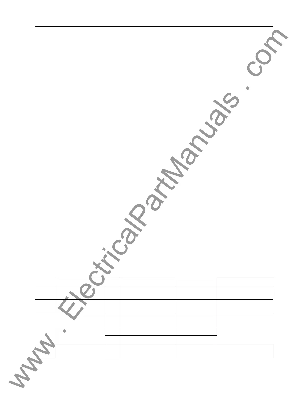
The table indicates region-specific presettings. Column C (configuration) indicates the
corresponding secondary nominal current of the current transformer.
Addr. Parameter C Setting Options Default Setting Comments
2901 MEASURE. SUPERV ON
OFF
ON Measurement Supervision
2902A BALANCE U-LIMIT 10 .. 100 V 50 V Voltage Threshold for
Balance Monitoring
2903A BAL. FACTOR U 0.58 .. 0.95 0.75 Balance Factor for Voltage
Monitor
2904A BALANCE I LIMIT 1A 0.10 .. 1.00 A 0.50 A Current Balance Monitor
5A 0.50 .. 5.00 A 2.50 A
2905A BAL. FACTOR I 0.10 .. 0.95 0.50 Balance Factor for Current
Monitor
www . ElectricalPartManuals . com

 Loading...


