2 Functions
62
7SD610 Manual
C53000-G1176-C145-4
2.3 Differential Protection
The differential protection is the main function of the device. It is based on current
comparison. For this, one device must be installed at each end of the zone to be pro-
tected. The devices exchange their measured quantities via communications links and
compare the received currents with their own. In case of an internal fault the allocated
circuit breaker is tripped.
Apart from normal lines, 7SD610 also enables protecting lines with transformers
switched en block (variant ordered). The protected zone is limited selectively by the
current transformer sets.
2.3.1 Function Description
Basic principle with
two ends
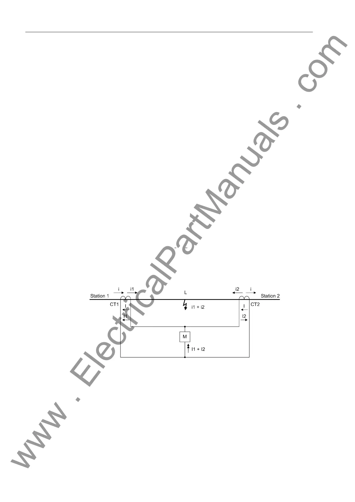
Differential protection is based on current comparison. It makes use of the fact that
e.g. a line section L (Figure 2-15) carries always the same current i (dashed line) at its
two ends in healthy operation. This current flows into one side of the considered zone
and leaves it again on the other side. A difference in current is a clear indication of a
fault within this line section. If the actual current transformation ratios are the same,
the secondary windings of the current transformers CT1 and CT2 at the line ends can
be connected to form a closed electric circuit with a secondary current I; a measuring
element M which is connected to the electrical balance point remains at zero current
in healthy operation.
When a fault occurs in the zone limited by the transformers, a current i
1
+ i
2
which is
proportional to the fault currents I
1
+ I
2
flowing in from both sides is fed to the measur-
ing element. As a result, the simple circuit shown in Figure 2-15 ensures a reliable trip-
ping of the protection if the fault current flowing into the protected zone during a fault
is high enough for the measuring element M to respond.
Figure 2-15 Basic principle of the differential protection for a line with two ends
Transmission
Measured Value
If the entire protected object is located in one place — as is the case with generators,
transformers, busbars — the measured quantities can be processed immediately. This
is different for lines where the protected zone spans a certain distance from one sub-
station to the other. To be able to process the measured quantities of all line ends at
each line end, these have to be transmitted in a suitable form. In this way, the tripping
condition at each line end can be checked and the respective local circuit breaker can
be operated if necessary.
7SD610 transmits the measured quantities as digital telegrams via communication
channels. For this, each device is equipped with one protection data interface.
www . ElectricalPartManuals . com

 Loading...


