2.15 Monitoring Functions
215
7SD610 Manual
C53000-G1176-C145-4
2.15.2 Trip Circuit Supervision
The line protection 7SD610 is equipped with an integrated trip circuit supervision func-
tion. Depending on the number of available binary inputs (not connected to a common
potential), supervision with one or two binary inputs can be selected. If the routing of
the binary inputs required for this does not comply with the selected supervision mode,
an alarm is given („TripC1 ProgFAIL ...“, with identification of the non-compliant cir-
cuit). When using two binary inputs, malfunctions in the trip circuit can be detected
under all circuit breaker conditions. When only one binary input is used, malfunctions
in the circuit breaker itself cannot be detected. If single-pole tripping is possible, a sep-
arate trip circuit supervision can be implemented for each circuit breaker pole provided
the required binary inputs are available.
2.15.2.1 Function Description
Supervision with
Two Binary Inputs
When using two binary inputs, these are connected according to Figure 2-90 parallel
to the associated trip contact on one side, and parallel to the circuit breaker auxiliary
contacts on the other.
A precondition for the use of the trip circuit monitoring is that the control voltage for the
circuit breaker is higher than the total of the minimum voltages drops at the two binary
inputs (U
Ctrl
> 2·U
BImin
). Since at least 19 V are needed for each binary input, the mon-
itoring function can only be used with a system control voltage of over 38 V.
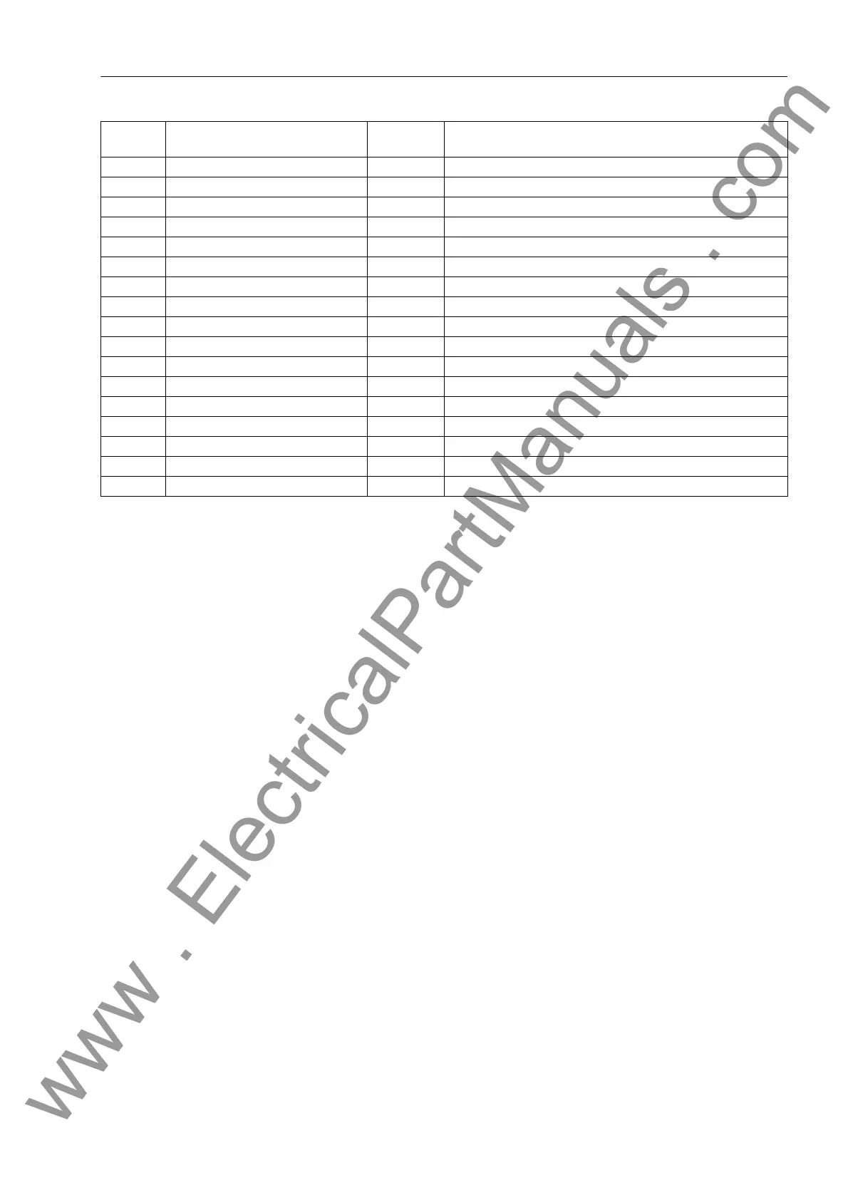
165 Fail Σ U Ph-E OUT Failure: Voltage summation Phase-Earth
167 Fail U balance OUT Failure: Voltage Balance
168 Fail U absent OUT Failure: Voltage absent
169 VT FuseFail>10s OUT VT Fuse Failure (alarm >10s)
170 VT FuseFail OUT VT Fuse Failure (alarm instantaneous)
171 Fail Ph. Seq. OUT Failure: Phase Sequence
196 Fuse Fail M.OFF OUT Fuse Fail Monitor is switched OFF
197 MeasSup OFF OUT Measurement Supervision is switched OFF
289 Failure Σi OUT Alarm: Current summation supervision
290 Broken Iwire L1 OUT Alarm: Broken current-wire detected L1
291 Broken Iwire L2 OUT Alarm: Broken current-wire detected L2
292 Broken Iwire L3 OUT Alarm: Broken current-wire detected L3
295 Broken wire OFF OUT Broken wire supervision is switched OFF
296 Σi superv. OFF OUT Current summation superv is switched OFF
297 ext.Brk.Wire L1 OUT Broken current-wire at other end L1
298 ext.Brk.Wire L2 OUT Broken current-wire at other end L2
299 ext.Brk.Wire L3 OUT Broken current-wire at other end L3
No. Information Type of In-
formation
Comments
www . ElectricalPartManuals . com

 Loading...


