2 Functions
216
7SD610 Manual
C53000-G1176-C145-4
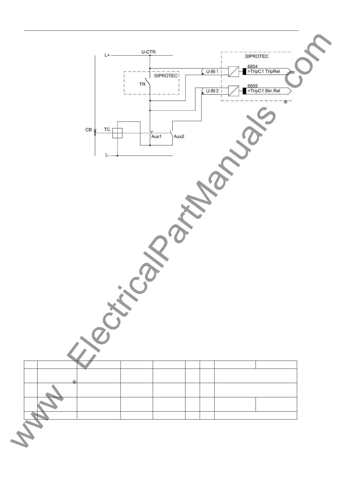
Figure 2-90 Principle of the trip circuit supervision with two binary inputs
TR Trip relay contact
CB Circuit breaker
TC Circuit breaker trip coil
Aux1 Circuit breaker auxiliary contact (NC contact)
Aux2 Circuit breaker auxiliary contact (NO contact)
U-CTR Control voltage (trip voltage)
U-BI1 Input voltage of 1st binary input
U-BI2 Input voltage of 2nd binary input
Monitoring with two binary inputs not only detects interruptions in the trip circuit and
loss of control voltage, it also supervises the response of the circuit breaker using the
position of the circuit breaker auxiliary contacts.
Depending on the conditions of the trip contact and the circuit breaker, the binary
inputs are activated (logical condition „H“ in the following table), or short-circuited (log-
ical condition „L“).
A state in which both binary inputs are not activated („L“) is only possible in intact trip
circuits for a short transition period (trip relay contact closed but circuit breaker not yet
open).
A continuous state of this condition is only possible when the trip circuit has been in-
terrupted, a short-circuit exists in the trip circuit, a loss of battery voltage occurs, or
malfunctions occur with the circuit breaker mechanism. Therefore, it is used as moni-
toring criterion.
Table 2-8 Condition table for binary inputs, depending on RTC and CB position
No. Trip Contact Circuit Breaker Aux 1 Aux 2 BI 1 BI 2 Dynamic State Static State
1 Open ON Closed Open H L Normal operation with circuit
breaker closed
2 Open OFF Open Closed H H Normal operation with circuit
breaker open
3 Closed ON Closed Open L L Transition or mal-
function
Malfunction
4 Closed OFF Open Closed L H TR has tripped successfully
www . ElectricalPartManuals . com

 Loading...


