2.4 Breaker Intertrip and Remote Tripping
77
7SD610 Manual
C53000-G1176-C145-4
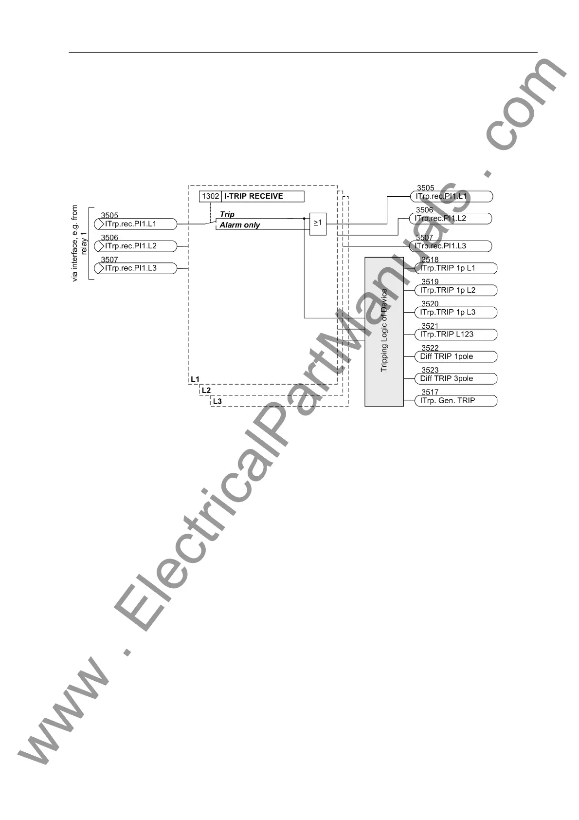
Receiving circuit On the receiving end the signal can lead to a trip. Alternatively it can also cause an
alarm only.
Figure 2-24 shows the logic diagram. If the received signal is to cause the trip, it will
be forwarded to the tripping logic. The tripping logic of the entire device (see also
Section 2.16.1) ensures, if necessary, that the conditions for single-pole tripping are
fulfilled (e.g. single-pole tripping permissible, auto-reclosure function ready).
Figure 2-24 Logic diagram of the intertrip — receiving circuit
Ancillary Functions Since the signals for remote tripping can be set to cause only an alarm, any other
desired signals can be transmitted in this way as well. After the binary input(s) have
been activated, the signals which are set to cause an alarm at the receiving end are
transmitted. These alarms can in turn execute any desired actions at the receiving
end.
It should be noted that for the transmission of remote alarms and remote commands
another 4 fast transmission channels are optionally available (see also Section 2.7).
2.4.2 Setting Notes
General The intertrip function for tripping caused by the differential protection can be activated
(YES) or deactivated (NO) with address 1301 I-TRIP SEND. Since the differential pro-
tection devices theoretically operate with the same measured values at both ends of
the protected object, a tripping in the event of an internal fault normally is also carried
out at both ends, regardless of the infeed conditions at the ends. In special cases, i.e.
if fault currents are to be expected near to the pickup threshold, it may occur that both
ends do not issue a tripping command due to inevitable device tolerances. For these
cases I-TRIP SEND = YES ensures the tripping at all ends of the protected object.
www . ElectricalPartManuals . com

 Loading...


