2.2 Protection Data Interfaces and Protection Data Topology
49
7SD610 Manual
C53000-G1176-C145-4
2.2 Protection Data Interfaces and Protection Data Topology
Devices protecting an object protected by current transformer sets, must exchange
data of the protected object.
This applies not only to the measured quantities relevant to the actual differential pro-
tection, but also to all data which are to be available at the ends. These data include
also topological data as well as the intertripping, transfer trip, remote annunciation
signals and measured values. The topology of the protected object, the allocation of
the devices to the ends of the protected object and the allocation of the ways of com-
munication to the protection data interfaces form the topology of the protection system
and its communication. Further details are available in the function description of the
differential protection (see Subsection 2.3).
2.2.1 Functional Description
2.2.1.1 Protection Data Topology / Protection Data Communication
Protection Data
Topology
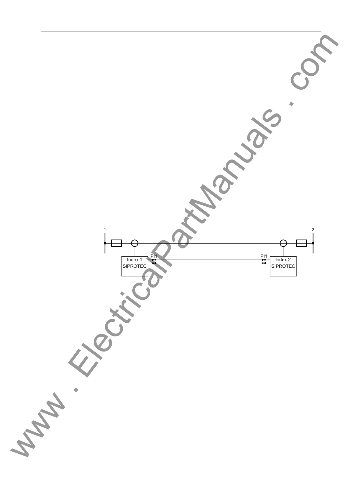
For a standard layout of lines with two ends, you require one protection data interface
(PI1) for each device (see also Figure 2-4).
Figure 2-4 Differential protection for two ends with two 7SD610 devices, each of them
having one protection data interface (transmitter/receiver)
Communication
media
Communication can occur via different communication connections. Which kind of
media is used depends on the distance and on the communication media available.
For distances up to 100 km a direct connection via optical fibres having a transmission
rate of 512 kbit/s is possible. Otherwise we recommend communication converters. A
transmission via modems and communication networks can also be realized. Please
note, however, that the tripping times of the differential protection devices depend on
the transmission quality and that they are prolonged in case of a reduced transmission
quality and /or an increased transmission time. Figure 2-5 shows examples of commu-
nication connections. In case of a direct connection the distance depends on the type
of the optical fibre. Table 2-2 lists the options available. The modules in the device are
replaceable. For ordering information see Appendix, under Accessories.
If a communication converter is used, the device and the communication converter are
linked with a FO5 module via optical fibres. The converter itself is available in different
versions allowing to connect it to communication networks (X.21, G703 64 kbit, G703
E1/T1) or connection via two-wire copper lines. For the Order No., please refer to the
Appendix under Accessories.
www . ElectricalPartManuals . com

 Loading...


