2.18 Command Processing
261
7SD610 Manual
C53000-G1176-C145-4
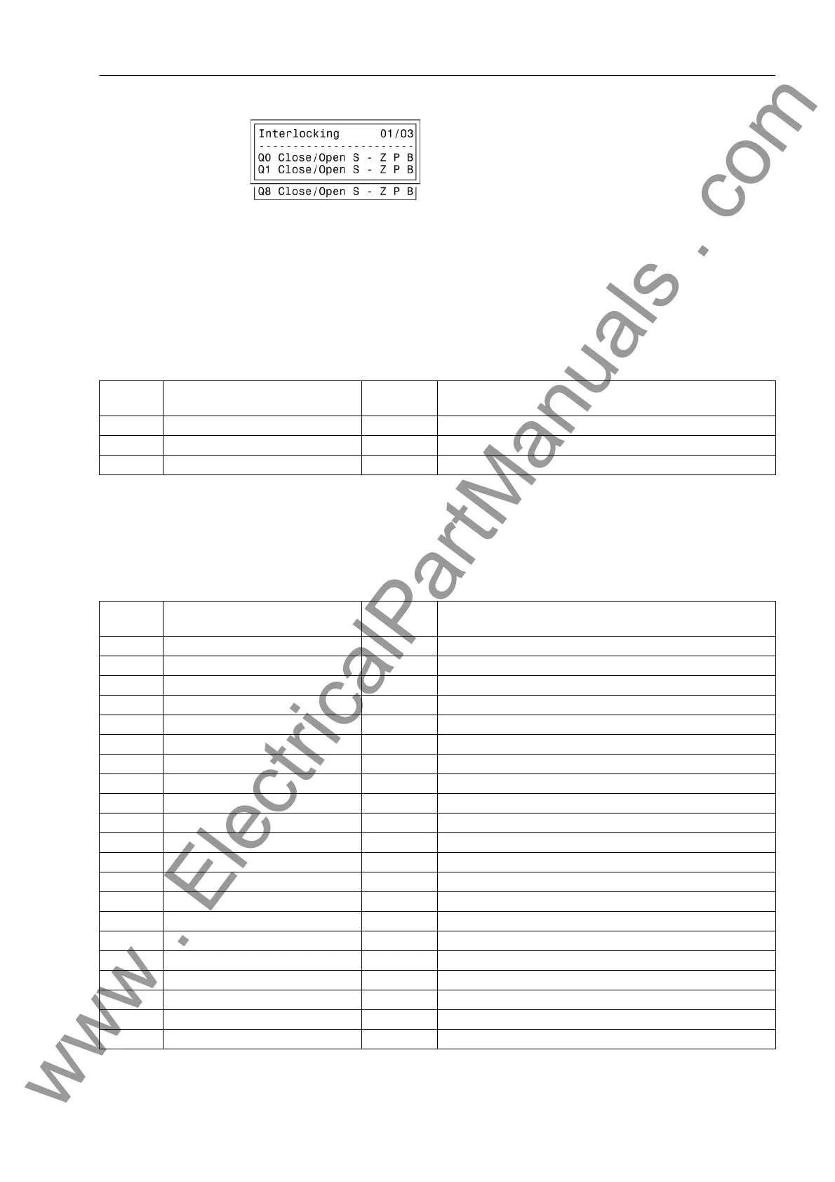
Figure 2-114 Example of configured interlocking conditions
Control Logic via
CFC
For the bay interlocking, an enabling logic can be structured using the CFC. Via spe-
cific release conditions the information „released“ or „bay interlocked“ are available,
e.g. object „52 Close“ and „52 Open“ with the data values: ON/OFF).
2.18.1.4 Information List
2.18.2 Control Device
2.18.2.1 Information List
No. Information Type of In-
formation
Comments
- ModeREMOTE IntSP Controlmode REMOTE
- Cntrl Auth IntSP Control Authority
- ModeLOCAL IntSP Controlmode LOCAL
No. Information Type of In-
formation
Comments
- Breaker CF_D12 Breaker
- Breaker DP Breaker
- Disc.Swit. CF_D2 Disconnect Switch
- Disc.Swit. DP Disconnect Switch
- EarthSwit CF_D2 Earth Switch
- EarthSwit DP Earth Switch
- Brk Open IntSP Interlocking: Breaker Open
- Brk Close IntSP Interlocking: Breaker Close
- Disc.Open IntSP Interlocking: Disconnect switch Open
- Disc.Close IntSP Interlocking: Disconnect switch Close
- E Sw Open IntSP Interlocking: Earth switch Open
- E Sw Cl. IntSP Interlocking: Earth switch Close
- Q2 Op/Cl CF_D2 Q2 Open/Close
- Q2 Op/Cl DP Q2 Open/Close
- Q9 Op/Cl CF_D2 Q9 Open/Close
- Q9 Op/Cl DP Q9 Open/Close
- Fan ON/OFF CF_D2 Fan ON/OFF
- Fan ON/OFF DP Fan ON/OFF
31000 Q0 OpCnt= VI Q0 operationcounter=
31001 Q1 OpCnt= VI Q1 operationcounter=
31002 Q2 OpCnt= VI Q2 operationcounter=
www . ElectricalPartManuals . com

 Loading...


