3.1 Mounting and Connections
285
7SD610 Manual
C53000-G1176-C145-4
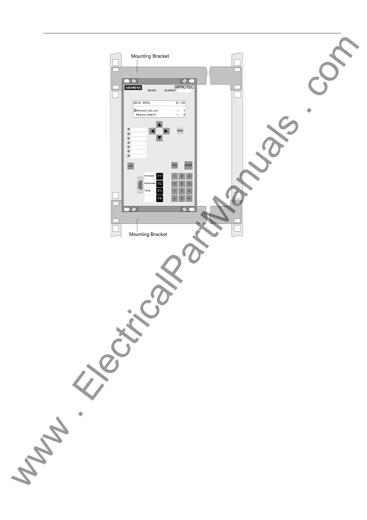
Figure 3-13 Example of rack or cubicle mounting of a device (housing size
1
/
3
)
3.1.3.3 Panel Mounting
For mounting proceed as follows:
• Secure the device to the panel with four screws. For dimensions see the Technical
Data in Section 4.17.
• Connect the low-resistance operational and protective earth to the ground terminal
of the device. The cross-sectional area of the ground wire must be equal to the
cross-sectional area of any other control conductor connected to the device. It must
thus be at least 2.5 mm
2
.
• Alternatively, there is the possibility to connect the aforementioned earthing to the
lateral grounding surface with at least one M4 screw.
• Connections according to the circuit diagram via screw terminals, connections for
optical fibres and electrical communication modules via the console housing. The
SIPROTEC 4 System Description has pertinent information regarding wire size,
lugs, bending radii, etc. Installation notes are also given in the brief reference
booklet attached to the device.
www . ElectricalPartManuals . com

 Loading...


