2 Functions
32
7SD610 Manual
C53000-G1176-C145-4
2.1.2 General Power System Data (Power System Data 1)
The device requires some plant and power system data in order to be able to adapt its
functions accordingly, dependent on the actual application. The data required include
for instance rated data of the substation and the measuring transformers, polarity and
connection of the measured quantities, if necessary features of the circuit breakers,
and others. Furthermore, there is a number of settings associated with several func-
tions rather than a specific protection, control or monitoring function. The Power
System Data 1 can only be changed from a PC running DIGSI and are discussed in
this section.
2.1.2.1 Setting Notes
Current
Transformer
Polarity
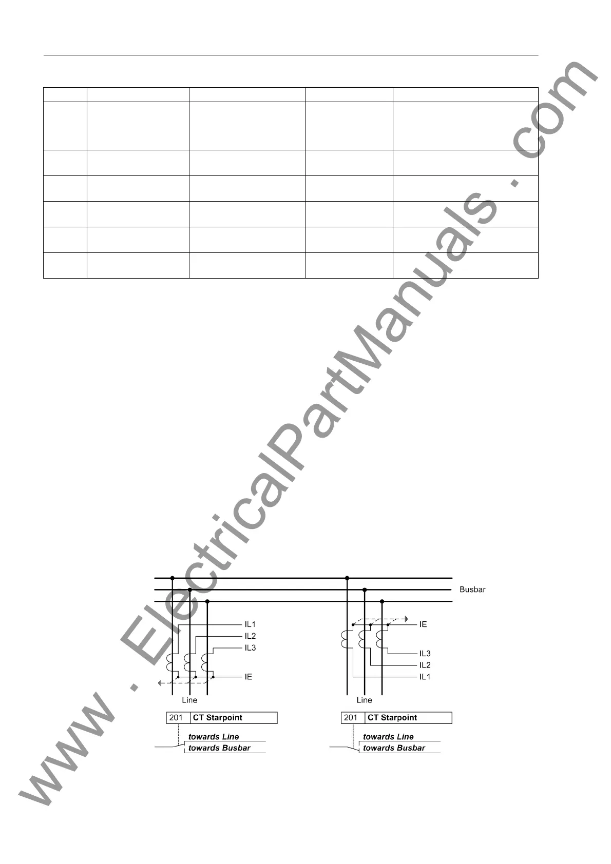
In address 201 CT Starpoint the polarity of the current transformers must be en-
tered, in other words, the location of the CT star-point (Figure 2-1). The setting defines
the measuring direction of the device (current in line direction is defined as positive at
both line ends). The reversal of this parameter also reverses the polarity of the residual
current input I
E
.
Figure 2-1 Polarity of current transformers
140 Trip Cir. Sup. Disabled
1 trip circuit
2 trip circuits
3 trip circuits
Disabled Trip Circuit Supervision
141 REF PROT. Disabled
Enabled
Disabled Restricted earth fault protection
142 Therm.Overload Disabled
Enabled
Disabled Thermal Overload Protection
143 TRANSFORMER NO
YES
NO Transformer inside protection
zone
144 V-TRANSFORMER Not connected
connected
connected Voltage transformers
148 GPS-SYNC. Enabled
Disabled
Disabled GPS synchronization
Addr. Parameter Setting Options Default Setting Comments
www . ElectricalPartManuals . com

 Loading...


