2 Functions
56
7SD610 Manual
C53000-G1176-C145-4
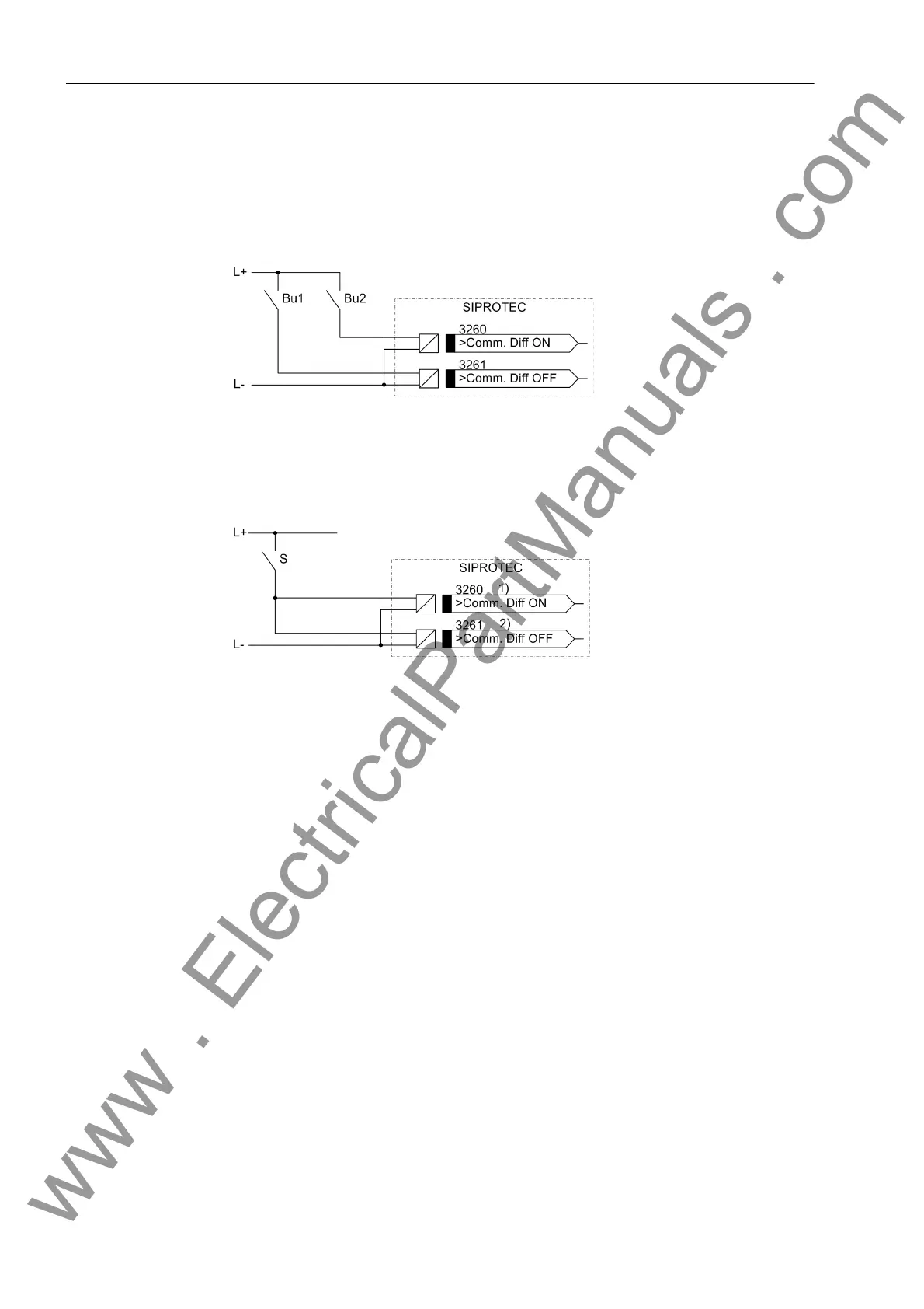
The following figures show possible variants for controlling the binary inputs. If a
switch is used for the control (Figure 2-13), it has to be observed that binary input
„>Comm. Diff ON“ (No. 3260) has to be parameterised as NO contact and that
binary input „>Comm. Diff OFF“ (No. 3261) has to be parameterised as NC con-
tact.
Figure 2-12 External button wiring for controlling the differential protection commissioning
mode
Bu1 Button „Deactivating differential protection commissioning mode“
Bu2 Button „Activating differential protection commissioning mode“
Figure 2-13 External switch wiring for controlling the differential protection commissioning
mode
S Switch „Activating/deactivating differential protection commissioning mode“
1) Binary input as NO contact
2) Binary input as NC contact
2.2.3 Protection Data Interfaces
2.2.3.1 Setting Notes
General Informa-
tion about
Interfaces
The protection data interfaces connect the devices with the communication media.
The communication is permanently monitored by the devices. Address 4509 T-DATA
DISTURB defines after which delay time the user is informed about a faulty or missing
telegram. Address 4510 T-DATAFAIL is used to set the time after which a transmis-
sion failure alarm is output. Address 4512 Td ResetRemote determines how long
time remote information remains standing after a transmission fault has been cleared.
Protection data
interface 1
The protection data interface 1 can be turned ON or OFF in address 4501 STATE PROT
I 1. If it is switched OFF, this corresponds to a transmission failure. The differential
protection and all functions which require the transmission of data, cannot work in this
case.
In address 4502 CONNEC. 1 OVER, set the transmission media that you want to
connect to protection data interface PI 1. The following selection is possible:
www . ElectricalPartManuals . com

 Loading...


