2 Functions
40
7SD610 Manual
C53000-G1176-C145-4
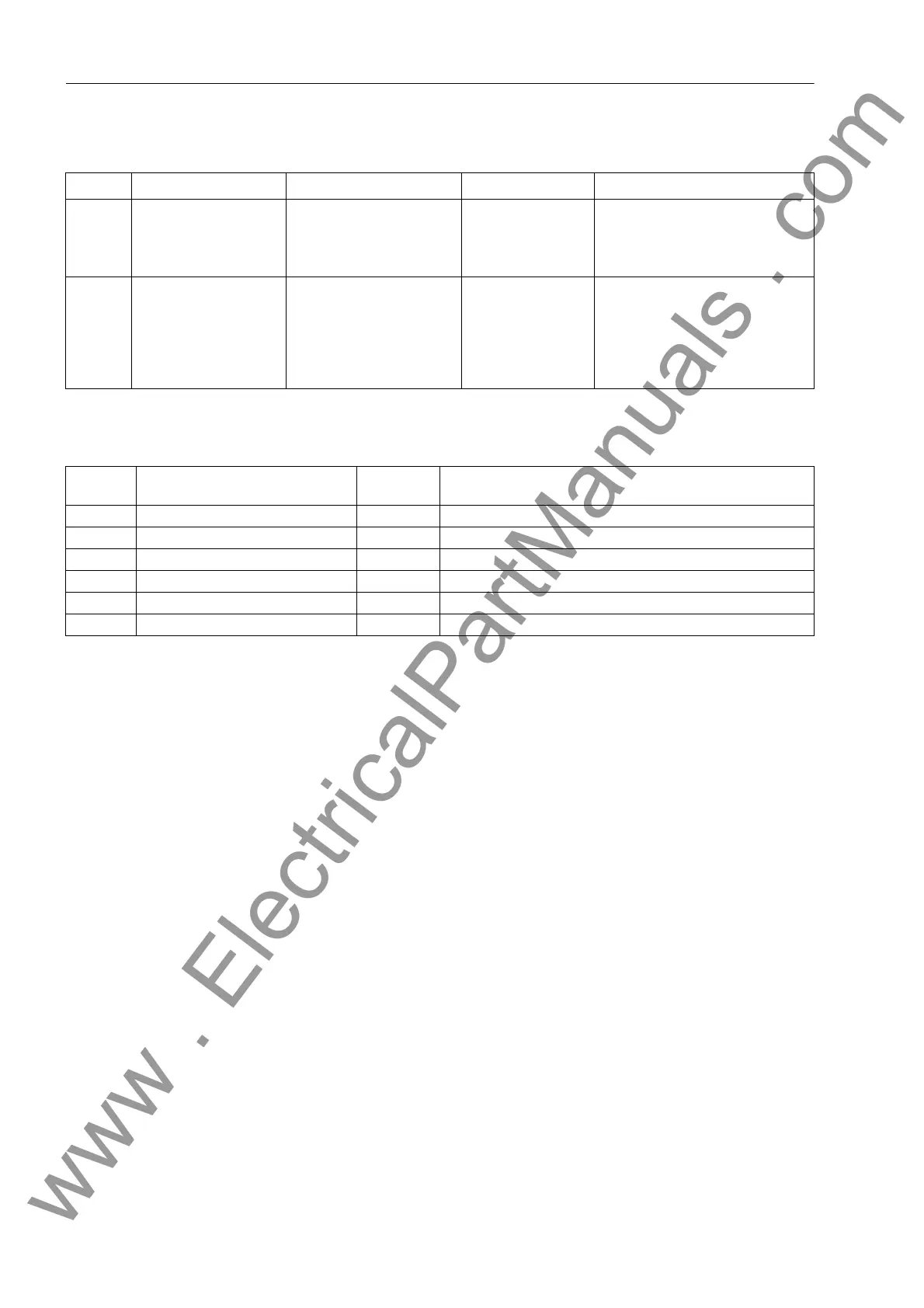
2.1.3.3 Settings
2.1.3.4 Information List
2.1.4 General Protection Data (Power System Data 2)
The general protection data (P.System Data 2) include settings associated with all
functions rather than a specific protection, monitoring or control function. In contrast
to the P.System Data 1 as discussed before, these can be changed over with the
setting groups and can be configured via the operator panel of the device.
To ensure uniform conversion factors of measured values for WEB-Monitor and
control centres, the setting of all operational rated values of the parameter groups
under P.System Data 2 should be identical.
2.1.4.1 Setting Notes
Rated values of
protected lines
The information under this margin heading refers to protected lines (cables or over-
head lines) if no power transformer is located within the protected zone, i.e. to models
without transformer option or if address 143 TRANSFORMER = NO has been set to,
Section 2.1.1.2).
With address 1103 FullScaleVolt. you inform the device on the primary rated
voltage (phase-to-phase) of the equipment to be protected (if voltages are applied).
This setting influences the displays of the operational measured values in %.
The primary rated current (address 1104 FullScaleCurr.) is that of the protected
object. For cables the thermal continuous current-loading capacity can be selected.
For overhead lines the nominal current is usually not defined; set the rated current of
the current transformers (as set in address 205 CT PRIMARY, Section 2.1.2.1). If the
Addr. Parameter Setting Options Default Setting Comments
301 ACTIVE GROUP Group A
Group B
Group C
Group D
Group A Active Setting Group is
302 CHANGE Group A
Group B
Group C
Group D
Binary Input
Protocol
Group A Change to Another Setting Group
No. Information Type of In-
formation
Comments
- Group A IntSP Group A
- Group B IntSP Group B
- Group C IntSP Group C
- Group D IntSP Group D
7 >Set Group Bit0 SP >Setting Group Select Bit 0
8 >Set Group Bit1 SP >Setting Group Select Bit 1
www . ElectricalPartManuals . com

 Loading...


