2 Functions
34
7SD610 Manual
C53000-G1176-C145-4
Connection of the
Currents
The device features four current measurement inputs, three of which are connected
to the set of current transformers. Various possibilities exist for the fourth current input
I
4
:
• Connection of the I
4
input to the earth current in the starpoint of the set of current
transformers on the protected feeder (normal connection):
Address 220 is then set to: I4 transformer = In prot. line and address
221 I4/Iph CT = 1.
• Connection of the I
4
input to a separate earth current transformer on the protected
feeder (e.g. a summation CT or core balance CT):
Address 220 is then set to: I4 transformer = In prot. line and address
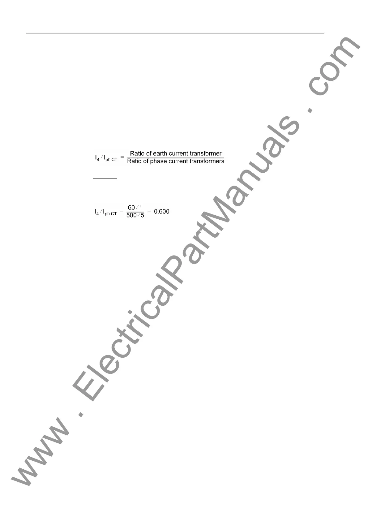
221 I4/Iph CT is set:
Example
:
Phase current transformers 500 A / 5 A
Earth current transformer 60 A / 1 A
• Connecting the I
4
input to the starpoint current of a transformator; this is used for
the earth fault differential protection:
Address 220 is then set to: I4 transformer = IY starpoint, and address 221
I4/Iph CT is according to transformation ratio of the starpoint transformer to the
transformer set of the protected line.
• If the input I
4
is not required, set:
Address 220 I4 transformer = Not connected,
Address 221 I4/Iph CT is then irrelevant.
In this case, the neutral current is calculated from the sum of the phase currents.
Rated frequency The nominal frequency of the system is set in address 230 Rated Frequency. The
presetting according to the ordering code (MLFB) only needs to be changed if the
device is applied in a region different to the one indicated when ordering. You can set
50 Hz or 60 Hz.
System Starpoint The manner in which the system starpoint is earthed must be considered for the
correct processing of earth faults and double earth faults. Accordingly, set for address
207 SystemStarpoint = Solid Earthed, Peterson-Coil or Isolated. For
low-resistant earthed systems set Solid Earthed.
Distance Unit Address 236 Distance Unit corresponds to the unit of length (km or Miles) appli-
cable to fault locating. If the compounding function of the voltage protection is used,
the overall line capacitance is calculated from the line length and the capacitance per
unit length. If compounding is not used, this parameter is of no consequence. Chang-
ing the length unit will not result in an automatic conversion of the setting values which
depend on this length unit. They have to be re-entered into their corresponding valid
addresses.
www . ElectricalPartManuals . com

 Loading...


