2.1 General
37
7SD610 Manual
C53000-G1176-C145-4
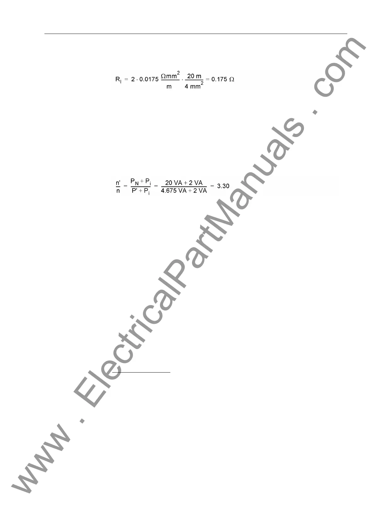
The resistance of the secondary lines is (with the resistivity for copper ρ
Cu
= 0.0175
Ωmm
2
/m)
Here, the most unfavourable case is assumed, i.e. the current (as it is the case with
single-phase faults) flows back and forth via the secondary lines (factor 2). From that
the power for nominal current I
N
= 5 A is calculated
P
l
= 0.175 Ω · (5 A)
2
= 4.375 VA
The entire connected burden consists of the burden of the incoming lines and the
burden of the device:
P' = 4.375 VA + 0.3 VA = 4.675 VA
Thus the ratio of the accuracy limit factors is as follows
According to the above table, address 251 is to be set to 1.5 if the calculated value is
higher than 1.5. This results in the following setting values:
Address 251 K_ALF/K_ALF_N = 1.50
Address 253 E% ALF/ALF_N = 3.0
Address 254 E% K_ALF_N = 10.0
The presettings correspond to current transformers 10P with rated burden.
Of course, only those settings are reasonable where address 253 E% ALF/ALF_N is
set lower than address 254 E% K_ALF_N.
Transformer with
voltage control
If a power transformer with voltage control is located in the protected zone, a differen-
tial current may occur even during normal healthy operation under steady-state con-
ditions. This differential current depends on the current intensity as well as on the po-
sition of the tap changer of the transformer. Since this differential current is current-
proportional it is meaningful to consider it like a current transformer error. You may cal-
culate the maximum differential current at the limits of the tap changer under nominal
conditions (referred to the mean current) and add it to the current transformer error as
discussed above (addresses 253 and 254). This correction is performed only at the
relay facing the regulated winding of the power transformer.
Calculation example:
Transformer YNd5
35 MV
110 kV / 25 kV
Y-winding with tap changer ±10 %
www . ElectricalPartManuals . com

 Loading...


