2 Functions
42
7SD610 Manual
C53000-G1176-C145-4
Calculation example:
Transformer YNd5
35 MVA
110 kV / 25 kV
Y-winding with tap changer ±10 %
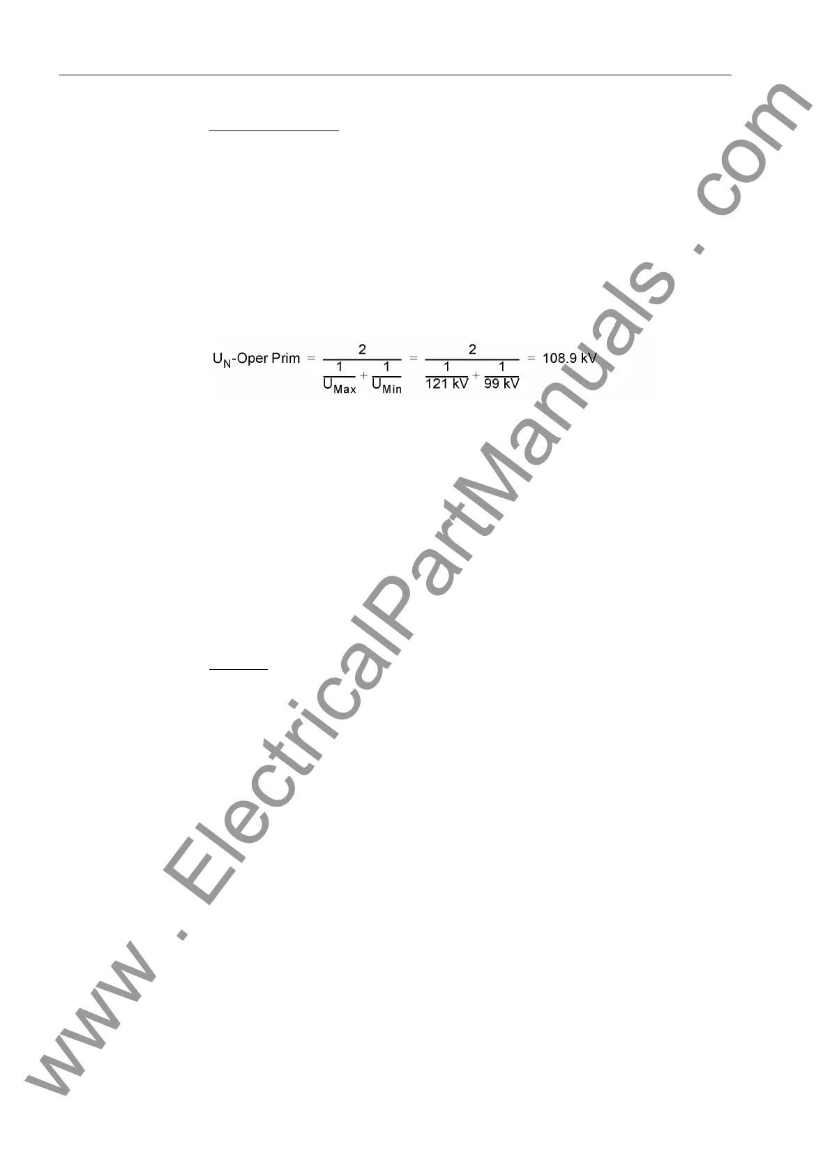
For the regulated winding (110 kV) this results in:
Maximum voltage U
max
= 121 kV
Minimum voltage U
min
= 99 kV
Voltage to be set (address 1103)
The OPERATION POWER (address 1106) is the direct primary rated apparent power
for transformers and other machines. For transformers with more than two windings,
state the winding with the highest rated apparent power. The same operation power
value must be set for each end of the protected object since it is the basis for the
current comparison at the ends.
The power must always be entered as primary value, even if the device is generally
configured in secondary values. The device calculates the primary rated current of the
protected device from the reference power.
The VECTOR GROUP I (address 1162) is the vector group of the power transformer,
always from the device's perspective. The device which is used for the reference end
of the transformer, normally the one at the high voltage side, must keep the numerical
index 0 (default setting). The relevant vector group index must be stated for the other
winding(s).
Example:
Transformer Yy6d5
For the Y end is set: VECTOR GROUP I = 0,
for the y end is set: VECTOR GROUP I = 6,
for the d end is set: VECTOR GROUP I = 5.
If a different winding is selected as reference winding, e.g. the d winding, this has to
be considered accordingly:
For the Y end is set: VECTOR GROUP I = 7 (12 - 5),
for the y end is set: VECTOR GROUP I = 6,
for the d end is set: VECTOR GROUP I = 0 (5 - 5 = 0 = reference side).
Address 1161 VECTOR GROUP U is normally set to the same value as address 1162
VECTOR GROUP I.
If the vector group of the transformer is adapted with external means, e.g. because
there are matching transformers in the measuring circuit that are still used, set
VECTOR GROUP I = 0 at all ends. In this case the differential protection operates
without proper matching computation. However, the measuring voltages transmitted
via the transformer would not be adapted in the device and therefore not be calculated
and displayed correctly. Address 1161 VECTOR GROUP U serves to remove this dis-
www . ElectricalPartManuals . com

 Loading...


