143/238
Building Technologies Modular Heating Controller RMH760B CE1P3133en
HVAC Products 9 Heating circuit control 05.02.2007
Requirement:
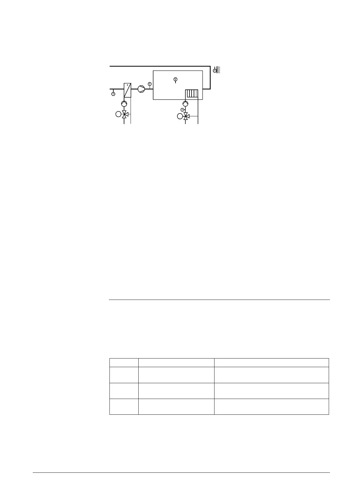
A heating circuit covers the basic load and a ventilation plant the individual load (heat
demand) in the space.
This application can also accommodate a common time switch or common preselected
operating modes, if required.
3131S61
Combination of ventilation and
heating
Solution:
Using the extra function “Room control combination“, the heating circuit can be oper-
ated as the slave and receives the room operating mode and the time program prede-
fined by the ventilation controller. It can be selected whether the setpoints for the
heating circuit shall be adopted externally (to be adjusted on the ventilation controller)
or internally (to be adjusted on the heating controller).
Heating circuit and ventilation must be assigned to the same geographical zone. A
room unit, if present, must also be assigned to the same geographical zone.
The ventilation controller
always assumes the function of the room control master.
A room unit, if present, always acts on the room control master.
During summer operation (heating circuit switched off via the heating limit), the ventila-
tion controller adopts the sustained mode.
Summer / winter operation changeover is ascertained via the heating limit (refer to
subsection
9.5.4) and sent to the ventilation controller via bus
The ventilation controller’s room temperature sensor must not be installed in the extract
air duct! Otherwise, functions ”Room temperature influence“ and “Optimization with
room temperature” are not allowed to be activated.
9.11 Fault handling
As soon as commissioning is completed (by quitting the Commissioning menu), a
check is made to see if the configured sensors are connected. Should a short-circuit or
open-circuit in connection with the sensor or the measuring line occur, a fault status
message will be delivered.
The number of the heating circuit or HC in the error text indicates the heating circuit or
aggregate where a fault occurred.
Number Text Effect
50 [HC 1] error flow sensor
Nonurgent message; must be acknowl-
edged
55 [HC 2] error flow sensor
Nonurgent message; must be acknowl-
edged
52 [Heat circuit 3] flow sens
error
Nonurgent message; must be acknowl-
edged
In the case of a faulty flow temperature sensor, the mixing valve will be driven to the
fully closed position to become inactive (3-position actuator), enabling it to be manually
operated.
Example:
Ventilation and heating
⇒
Summer operation
Important
Faulty flow
temperature sensor

 Loading...


