TXP CLC Course
6
TXP Training Project
Engineering Procedure
The engineering procedure can be subdivided as follows:
-- Entering project data (complete for this training project)
-- Drawing equipment structure, AS structure and module structure
-- Drawing the ”measurement” function diagrams
-- Drawing area and overview diagrams (optional)
-- Drawing function diagrams
-- Generating the code and transferring to the target system
This chapter will only cover the first and second and fourth procedures. The other
procedures will be covered in subsequent chapters.
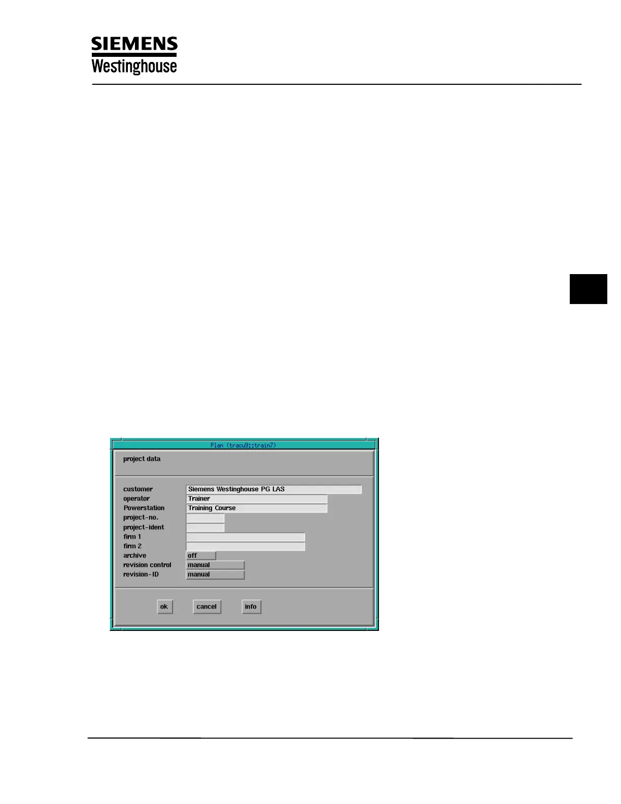
1 Entering the Project Data
Before the diagrams are generated, the general project data has to be entered
(DB -- Defaults – Project data).In this section you assign the project name,
engineer , Power Station, Project number , etc. This information will be added to
each function diagram subsequently created in the project.
The functional complexes (major areas of the power plant) are then entered and
assigned to users for processing and also to AS numbers (DB -- Defaults -- FB
data). This assignment is a default that is used if no data is entered in the
function group code (sub-areas of the power plant) mask that has to be
completed next (DB--fct. -- Defaults – FGC data). The AS and AP-F numbers that
are entered here are defaults that are used when a new diagram is created.
Training Center
Copying of this document, and giving it to others and use or communication of the contents, are forbidden without express authority. Offenders are liable to the payment of
damages. All rights are reserved in the event of the grant of a patent or the registration of a utility model or design.
1