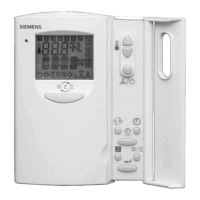
Do you have a question about the Siemens TXP-CLC and is the answer not in the manual?
Network communication paths within the TXP system.
TXP system components and their interconnections.
Hierarchical levels of TXP components from field to operating.
Overview of AS620 system types (B, F, T) and their functions.
Details on FUM and SIM module configurations for AS620 B.
Specific functions and applications of the AS620 T automation system.
Components and layout of the AS620 standard cabinet.
Summary of key features and benefits of the AS620 system.
Advantages and features of TXP's Industrial Ethernet network.
Design principles and operational modes of the Industrial Ethernet bus.
How Industrial Ethernet achieves high availability and fault tolerance.
Implementation of time synchronization using Industrial Ethernet.
Key features and benefits of using Industrial Ethernet in TXP.
Overview of ES680 as an integrated planning and commissioning tool.
Engineering process and documentation within the ES680 environment.
How AS620 hardware is represented using logic diagrams in ES680.
Hierarchical structure of arrangement diagrams for hardware definition.
Summary of key features and capabilities of the ES680 engineering system.
System for identifying equipment and documentation using tagging.
Levels and numbering systems within the KKS tagging.
Codes used to classify functions and systems within KKS.
Codes used to classify equipment based on its function or type.
Codes categorizing electrical components within the KKS system.
General rules for numbering KKS equipment codes, especially for fittings.
System for coding cables based on function, unit, and serial number.
Using KKS for identifying documentation and signal standards.
Suffix to KKS code identifying switching element type for signal creation.
Overview of the engineering procedure for creating TXP projects.
Detailed steps within the TXP engineering process.
Process of inputting general project information into the system.
Types of diagrams used for representing project structure (topology, AS, individual).
Process of configuring hardware modules and channels in diagrams.
General description and application of the BT function block for binary signals.
List of outputs from the BT function block to other diagrams.
Explanation of parameters used to configure the BT function block.
Step-by-step guide to creating signal definitions for connections.
General description and application of the AT function block for analog signals.
List of outputs from the AT function block to other logic diagrams.
List of inputs to the AT function block from other logic diagrams.
Detailed explanation of parameters for the AT function block.
General description and application of the CBO function block for binary outputs.
List of outputs provided by the CBO function block.
Explanation of parameters for the CBO function block.
General description and application of the CAO function block for analog output signals.
List of outputs provided by the CAO function block.
Detailed explanation of parameters for the CAO function block.
General description and application of the DCM function block for motor/solenoid valve control.
Explanation of different operating modes for the DCM function block.
Overview of manual command generation and output logic for drives.
Logic diagrams illustrating drive command generation.
Steps for generating code from drawings using ES680.
Process for transferring generated code to CP and AP.
Procedure for compiling MMI pictures for the operator interface.
Process for generating the BDM text database for KKS signals.
Method for identifying and completing open signal connections in diagrams.
| Product type designation | TXP-CLC |
|---|---|
| Digital output type | Relay |
| Protection class | IP20 |
| Manufacturer | Siemens |
| Category | Control Systems |
| Mounting type | DIN rail |
| Analog input type | 0-10 V |
| Function | Control and monitoring |
| Type | Central Logic Controller |


