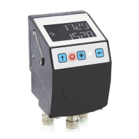
AP10S
Date: 04.09.2017 Art. No. 87826 Mod. status 269/17 Page 3 of 48
6.3.2 Node address ...................................................................................................... 19
6.3.3 Parameter address ............................................................................................... 19
6.3.4 Control word ...................................................................................................... 20
6.3.5 Status word ........................................................................................................ 20
6.3.6 Data .................................................................................................................. 21
6.3.7 Check sum .......................................................................................................... 21
6.4 Synchronization ..................................................................................................... 22
6.5 Error telegram ........................................................................................................ 22
6.5.1 SIKONETZ5 error codes ......................................................................................... 22
6.6 Communication errors ............................................................................................. 23
6.7 Communication monitoring ...................................................................................... 23
6.7.1 Bus-Timeout ....................................................................................................... 23
6.7.2 Programming interlock ......................................................................................... 23
6.8 Auto-ID ................................................................................................................. 24
6.9 Parameter description ............................................................................................. 26
6.9.1 00h: Node address ............................................................................................... 26
6.9.2 01h: Baud rate ................................................................................................... 26
6.9.3 02h: Bus Timeout ................................................................................................ 26
6.9.4 03h: Response parameter to a set point write access ................................................ 27
6.9.5 04h: Keys enable time: Configuration start delay ..................................................... 27
6.9.6 05h: Key function enable1: Calibration enable ......................................................... 27
6.9.7 06h: LED flashing ................................................................................................ 28
6.9.8 07h: LED3 (green right) ....................................................................................... 28
6.9.9 08h: LED2 (red left) ............................................................................................ 28
6.9.10 09h: LED1 (green left) ......................................................................................... 29
6.9.11 0Ah: Decimal places ............................................................................................ 29
6.9.12 0Bh: Display divisor (ADI) .................................................................................... 29
6.9.13 0Ch: Direction indicators (CW, CCW) ....................................................................... 30
6.9.14 0Dh: Display orientation ...................................................................................... 30
6.9.15 0Eh: Configuration programming mode ................................................................... 30
6.9.16 1Bh: Counting direction ....................................................................................... 31
6.9.17 1Ch: Resolution or measurement steps per revolution ............................................... 31
6.9.18 1Eh: Offset value ................................................................................................ 32
6.9.19 1Fh: Calibration value .......................................................................................... 32
6.9.20 20h: Target window1 (near field) .......................................................................... 33
6.9.21 21h: Positioning type (loop type) .......................................................................... 33
6.9.22 22h: Loop length ................................................................................................ 33
6.9.23 28h: Operating mode ........................................................................................... 34
6.9.24 30h: Display in the 2
nd
row ................................................................................... 34
6.9.25 31h: Target window2 (extended) ........................................................................... 35
6.9.26 32h: Target window2 visualization ......................................................................... 35
6.9.27 33h: Application of the display divisor (ADI application) .......................................... 35
6.9.28 34h: Formation of the differential value ................................................................. 36
6.9.29 35h: Key function enable2: Incremental measurement enable .................................... 36