- 15 -
No.EX※※-OMW0011-B
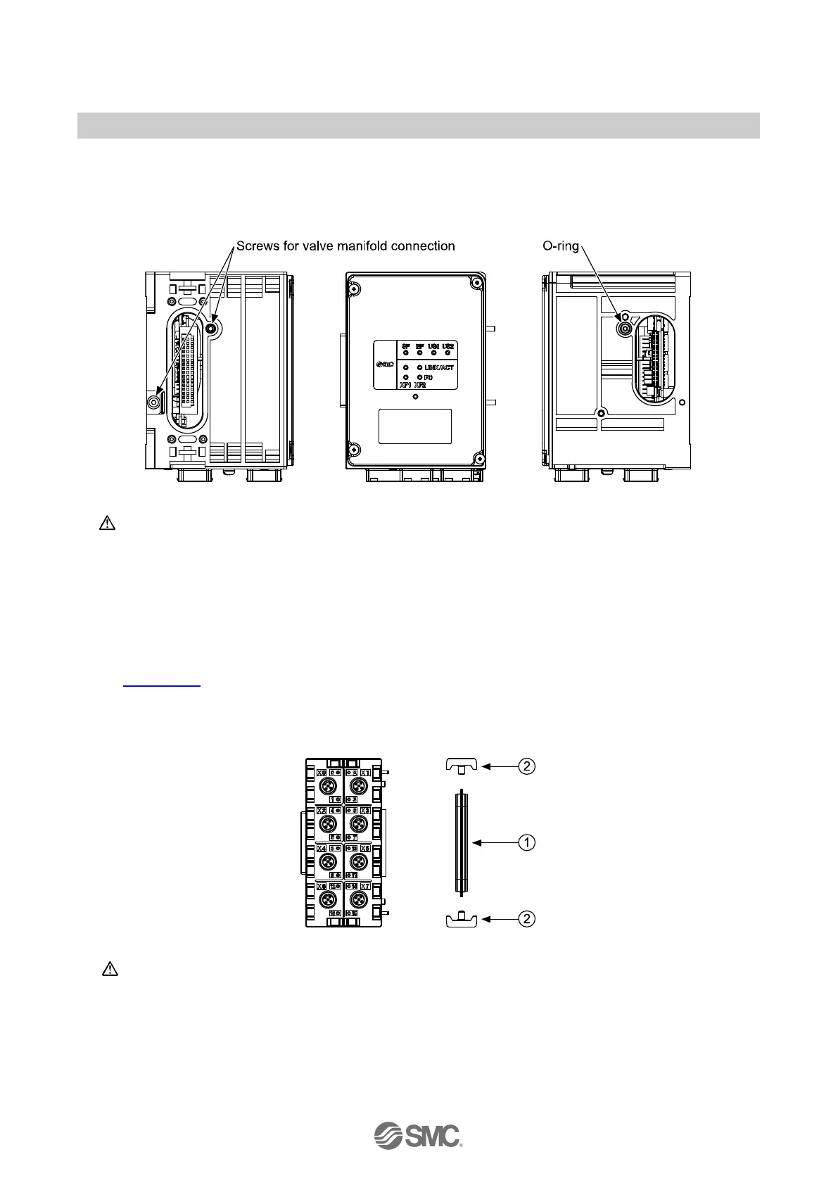
3.1.1. Valve manifold connection
Connect the valve manifold with the 2 screws on the SI Unit. (hexagonal socket wrench size 2.5)
For torque value, refer to valve manifold catalogue.
Fig. 3-2 Valve manifold connection
Caution
・ For a protection rating of IP65 to be ensured, apply the recommended tightening torque and
make sure that the O-ring is positioned correctly on the screw.
3.1.2. Module connection
Connect the SI Unit, the Input/Output modules, the IO-Link modules and the End plate with the 2
modular adaptor assemblies and the joint assembly. These are grouped together in the Joint pack, refer
to Section 11.4
.
① 1 x Joint assembly
② 2 x Modular adaptor assembly (hexagonal socket wrench size 2.5, torque = 1.3 N•m)
Fig. 3-3 Module connection
Caution
・ For a protection rating of IP65 to be maintained, the End plate must be installed on the end of
module side correctly.
・ For a protection rating of IP65 to be ensured, modular adaptor assemblies and joint assembly
must be installed between each module correctly.
・ To prevent the modules and assemblies being damaged, apply the recommended tightening
torque.
 Loading...