- 30 -
No.EX※※-OMW0011-B
5. Diagnosis
5.1. Diagnostics data on I/O mapping
The SI Unit can be allocated diagnostics data as digital input data on I/O mapping, if one of the
module, Diagnostics type 1 or Diagnostics type 2, is configured. Use PROFINET IO Controller’s
software to select a requested diagnostics type to allocate the diagnostics data on I/O mapping.
The IO-Link modules EX245-LA1 / LB1 has diagnostics data (PQI) as digital input data on I/O
mapping. Refer to Section 9.7
.
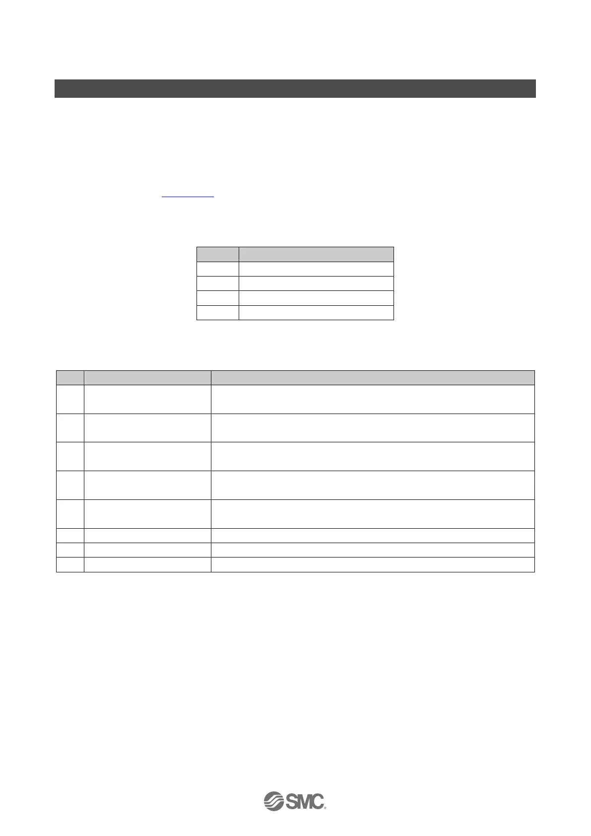
5.1.1. Diagnostics type 1
Table. 5-1 Overview of Diagnostics type 1
3 Valve diagnostics 2
・ General diagnostics 1
Table. 5-2 General diagnostics 1
0 System fault
0: No error on Diagnostics data on I/O mapping
1: At least one error on Diagnostics data on I/O mapping has occurred
1 Valve-coil(s) short circuit
0: No valve coil(s) have a short circuit
1: At least one valve coil has a short circuit
2 Module error
0: No module has an error
1: At least one connected module has an error
3 Changed module layout
0: Module has not disconnected.
1: At least one module has disconnected.
4 US1 Diagnostics
0: US1 present
1: US1 has dropped (< approx. 19.2V DC)
6 Reserved Fixed 0
 Loading...