- 53 -
No.EX※※-OMW0011-B
8.3. Wiring
Caution
・ To prevent damage, all power for the SI Unit and modules must be turned off (i.e. de-energized)
before the modules are installed or removed.
・ For a protection rating of IP65 to be ensured, all covering caps must be screwed down correctly
after wiring and setting have been performed.
・ For a protection rating of IP65 to be ensured, sockets that are not used must be fitted with the
Seal cap.
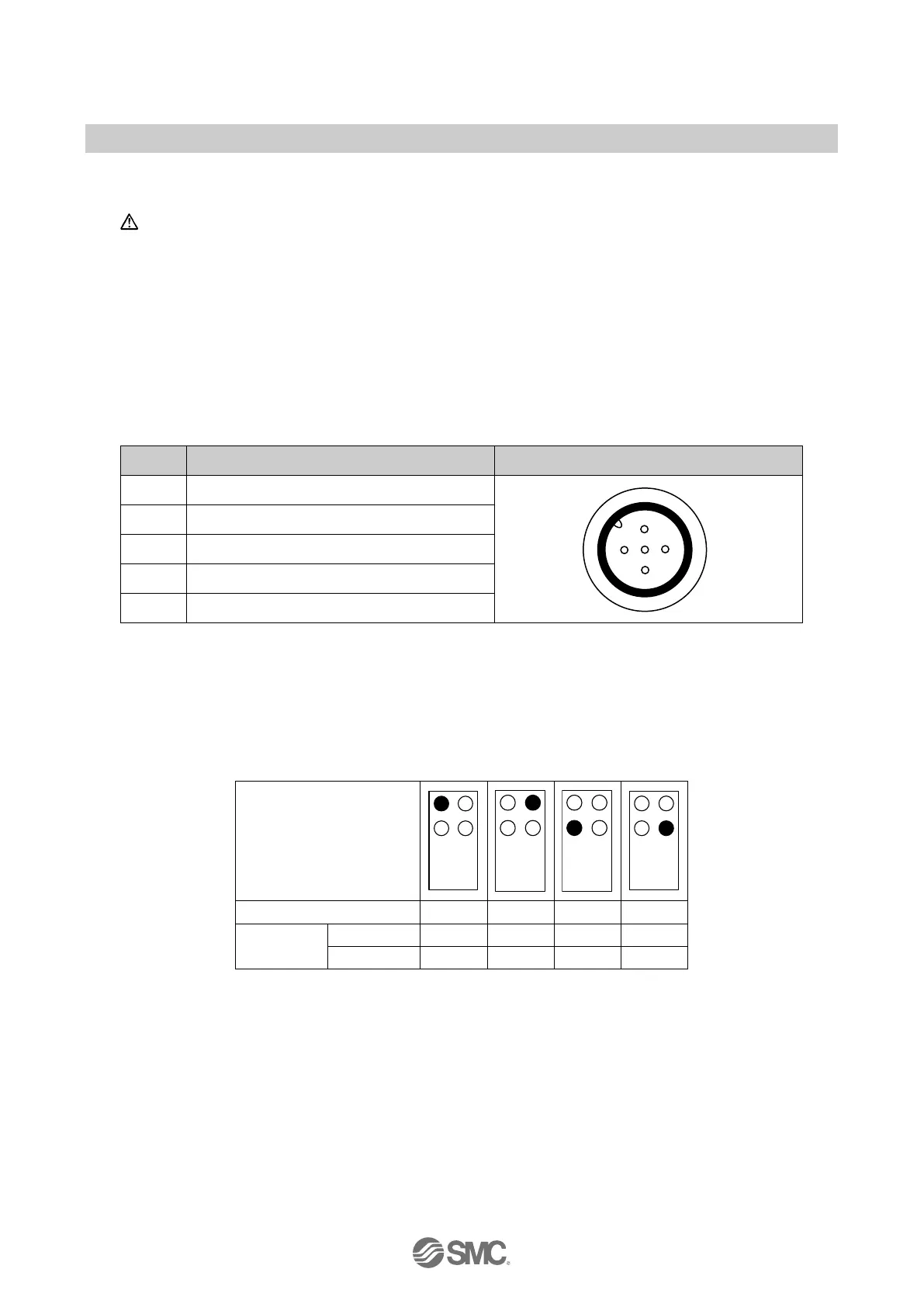
Pin allocation of the M12, 5 pins socket connector as shown in the following table:
Table. 8-2 Pin allocation of the connector for EX245-DY1
Pin Allocation View of connector (module side)
1 N.C.
2 DO (output signal "n+1", US2)
3 0 V (US2)
4 DO (output signal "n", US2)
5 FE/Shield
8.4. Process data
The EX245-DY1 occupies 1 byte of output data. The following table shows the allocation of the
digital outputs and the process image.
Table. 8-3 Digital output allocation and the process data
Connector position
Output
Pin 4 Bit 0 Bit 2 Bit 4 Bit 6
 Loading...