- 83 -
No.EX※※-OMW0011-B
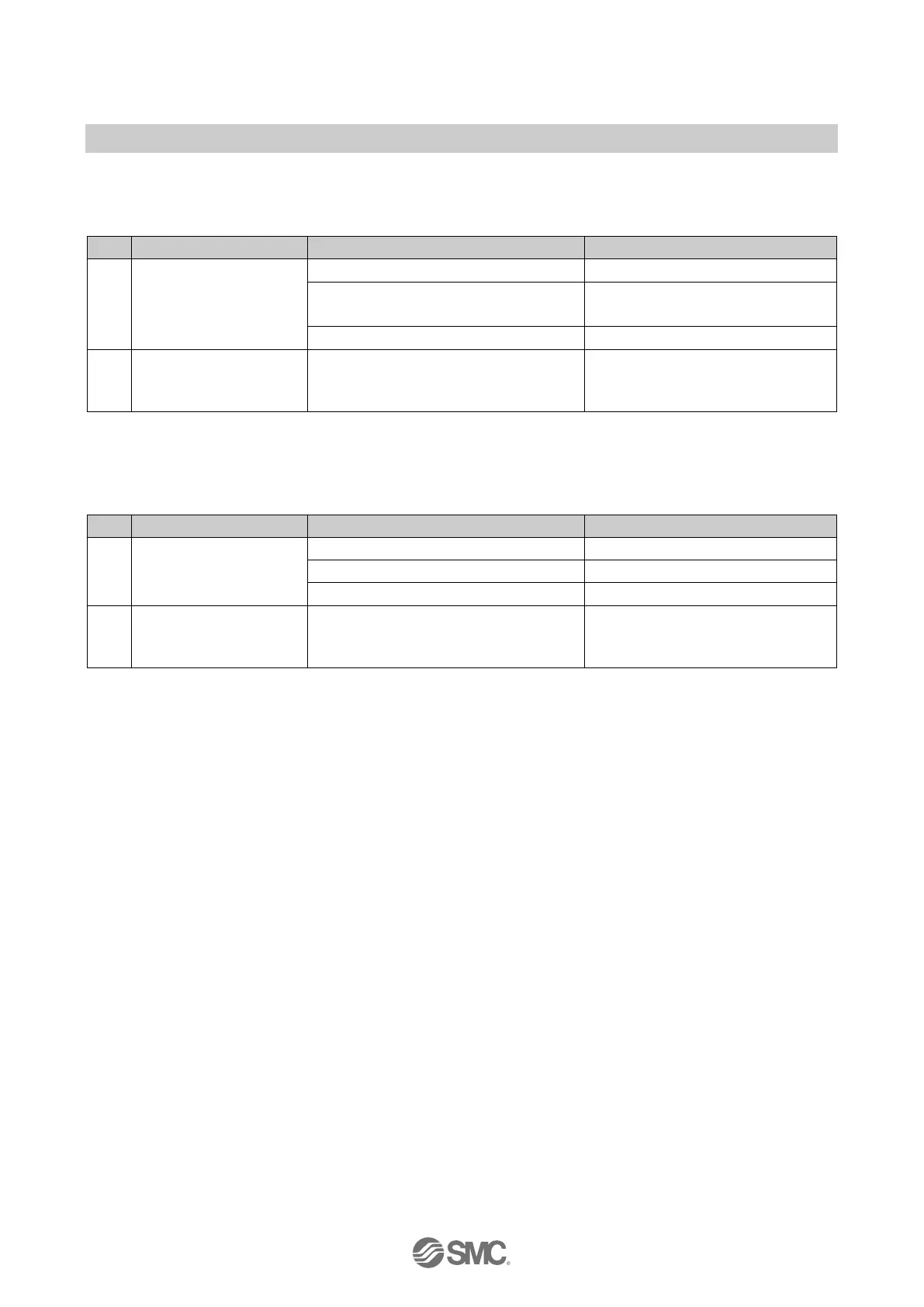
13.2. EX245-DX1
Table. 13-7 Troubleshooting for EX245-DX1
1
Signals cannot be
received even with
sensor.
Check the wiring and pin numbers.
US1 is not present.
Check the supply for US1
(sensor/input).
2
Status indicator is red
ON.
"Pin 1: 24 V" and "Pin 3: 0 V" of the
sensor connection have over current.
Check the sensor.
Check the cable.
Check the wiring and pin numbers.
13.3. EX245-DY1
Table. 13-8 Troubleshooting for EX245-DY1
1 A load is not operating.
Check the wiring and pin numbers.
Check the supply for the loads.
2
ON.
"Pin 2/4: output signal" and "Pin 3: 0 V"
of the load connection have over
current.
Check the load.
Check the cable.
Check the wiring and pin numbers.
 Loading...