- 40 -
No.EX※※-OMW0011-B
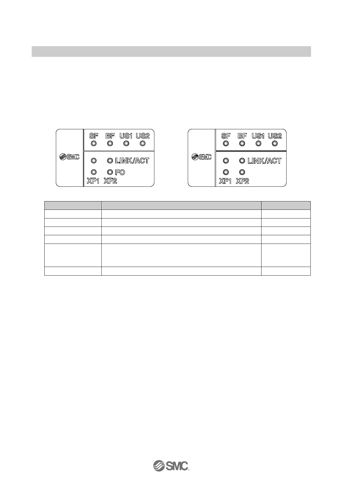
6.4. LED indicators
The LED indicators are arranged on the SI Unit as shown in the illustration below.
The layout of the LINK/ACT LEDs and FO LEDs are for port1 on the left side (XF1) and for port2 on
the right side (XF2).
EX245-SPN1A EX245-SPN2A/EX245-SPN3A
Designation Description Colour
US1 Supply for the logic/sensors Green
Supply for the valves/loads
LINK/ACT
A combination of LINK LED and ACT LED
Connection status via Ethernet (LINK: Green)
Data exchange status (ACT: Orange)
Green/Orange
Fibre-Optic communication diagnostics
Fig. 6-4 LED indicators of the SI Unit
 Loading...