- 41 -
No.EX※※-OMW0011-B
6.4.1. SF and BF indicators
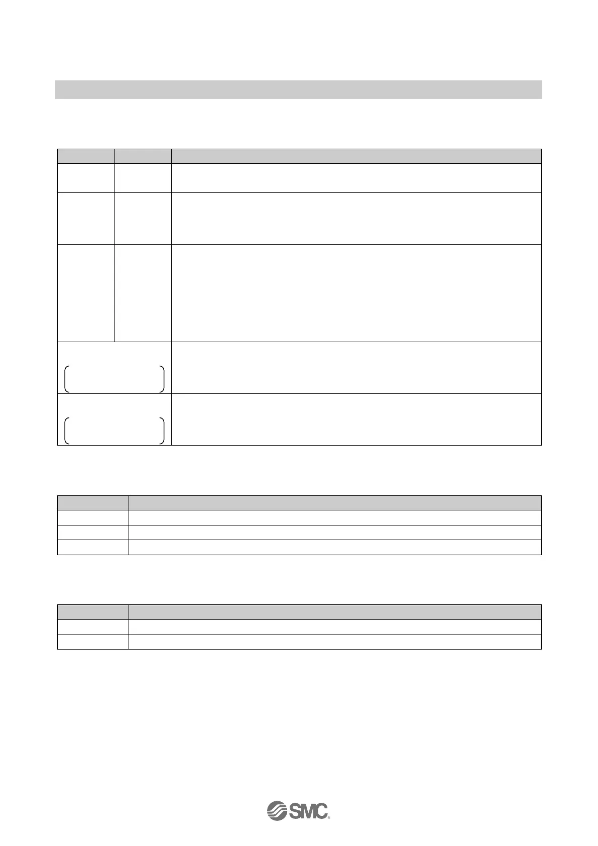
Table. 6-3 SF and BF indicators
OFF OFF
No fault (The SI Unit is currently exchanging data with the IO Controller without
errors).
ON ---
One of the following may have occurred.
・ US1 is below the permissible level (< approx. 19.2 VDC).
・ The valve coil has a short circuit or the connected module has a short circuit.
・
The connected module has disconnected.
--- ON
One of the following may have occurred.
・ The connection to the IO Controller is nothing, or disconnection to the IO
Controller.
・ Device name is not correct.
・ IP address is not set or not correct.
・ The GSD file is not correct.
・
The configuration data sent by the IO Controller does not match the actual
at 1 Hz
One of the following may have occurred.
・ During firmware update.
・ During forced output mode by Web server function.
at 1 Hz
Firmware update failed.
6.4.2. US1 indicator
Table. 6-4 US1 indicator
US1 is present but is below the permissible level (< approx. 19.2 VDC).
6.4.3. US2 indicator
Table. 6-5 US2 indicator
OFF US2 is not present.
SF ON SF OFF
BF ON BF OFF
SF ON SF OFF
BF OFF BF ON
 Loading...