- 59 -
No.EX※※-OMW0011-B
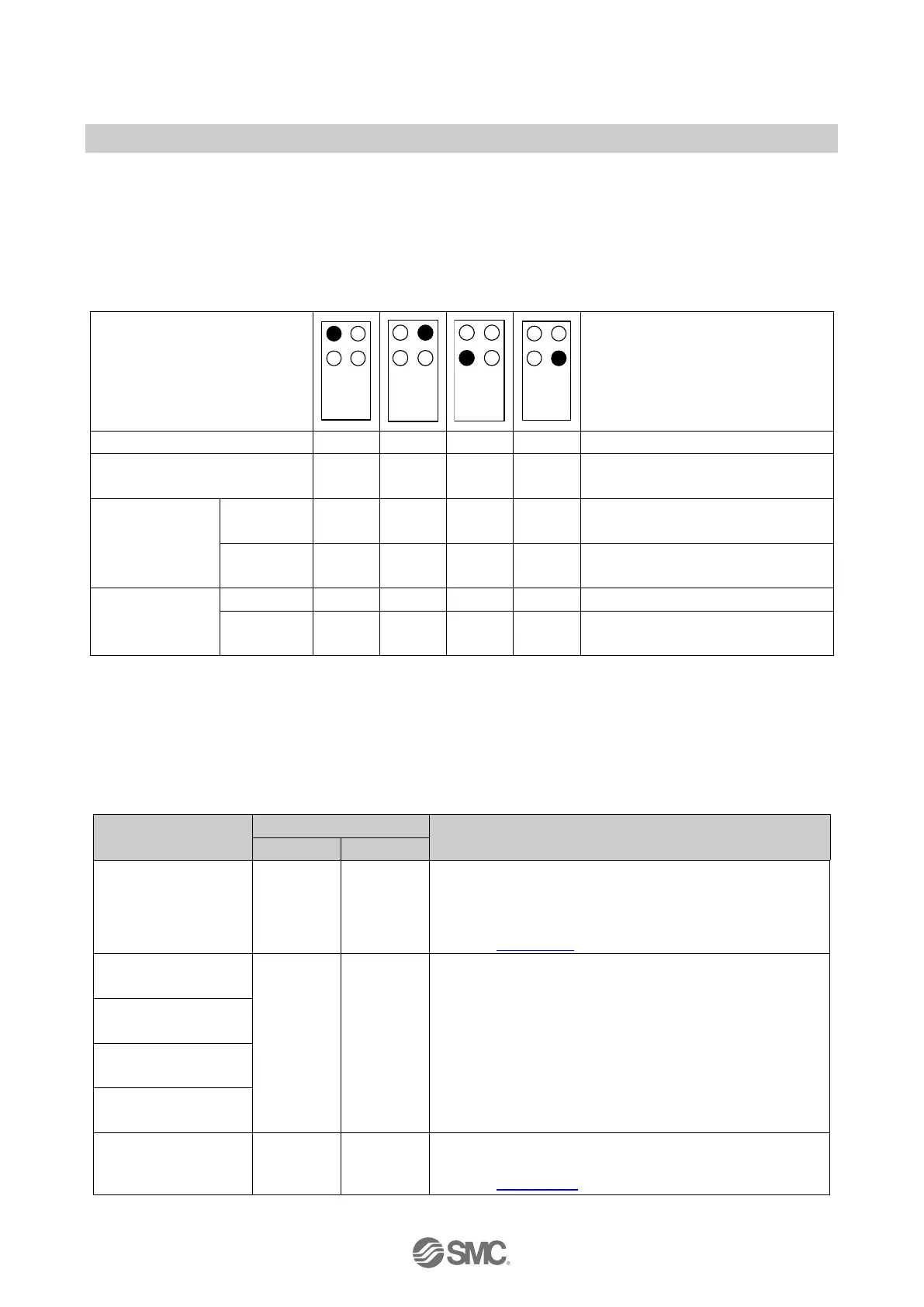
9.4. Connector allocation and process data
IO-Link port numbers and Connector designation are arranged as follows.
The EX245-LA1 / LB1 occupies 2 bytes of I/O process data on the Standard IO slot. The following
table shows the allocation of the IO-Link ports and the I/O process image.
Table. 9-4 Connector allocation and the process data
Connector position
Note
Connector designation X0 X1 X2 X3 -
IO-Link port number 1 2 3 4
Available when the IO-Link device
sub-module is configured.
Digital input
Pin 2
(I/Q)
Byte N
Bit 1
Byte N
Bit 3
Byte N
Bit 5
Byte N
Bit 7
EX245-LA1 only
(For EX245-LB1 bits are fixed at 0)
Pin 4
(C/Q)
Byte N
Bit 0
Byte N
Bit 2
Byte N
Bit 4
Byte N
Bit 6
Available when the Digital input
sub-module is configured.
Digital output
Pin 4
(C/Q)
Byte N
Bit 0
Byte N
Bit 2
Byte N
Bit 4
Byte N
Bit 6
Available when the Digital output
sub-module is configured.
∗: Input and Output Byte N+1 is fixed at 0x00.
9.5. Slot structure
EX245-LA1 / LB1 has the slots as follow.
Table. 9-5 Overview of slot structure
Slot number
∗
Description
1
st
slot
(Standard IO)
2 2
The I/O process data are allocated when set the Digital
input/output sub-modules in the 2
nd
to 5
th
slot.
The input process data on pin 2 (I/Q) is allocated when
using the EX245-LA1.
2
nd
Slot:
(Config. for port 1)
Depend
on
configu-
ration
Depend
on
configu-
ration
The IO-Link device or Digital input/output sub-module
can be configured for each slot.
By default, all IO-Link ports are deactivated.
To enable an IO-Link port, delete the sub-module ‘Port
deactivated’ and replace it with one of the following
sub-modules
‘IO-Link Device’, or
‘Digital Input’, or
‘Digital Output’.
3
rd
Slot:
(Config. for port 2)
4
th
Slot:
(Config. for port 3)
5
th
Slot:
(Config. for port 4)
6
th
slot
(PQI)
4 0
The diagnostic information for each port is shown as
input process data in 1 Byte per port.
Refer to Section 9.7.
∗: The name is displayed in Siemens software TIA Portal.
 Loading...