- 67 -
No.EX※※-OMW0011-B
9.10. LED indicators
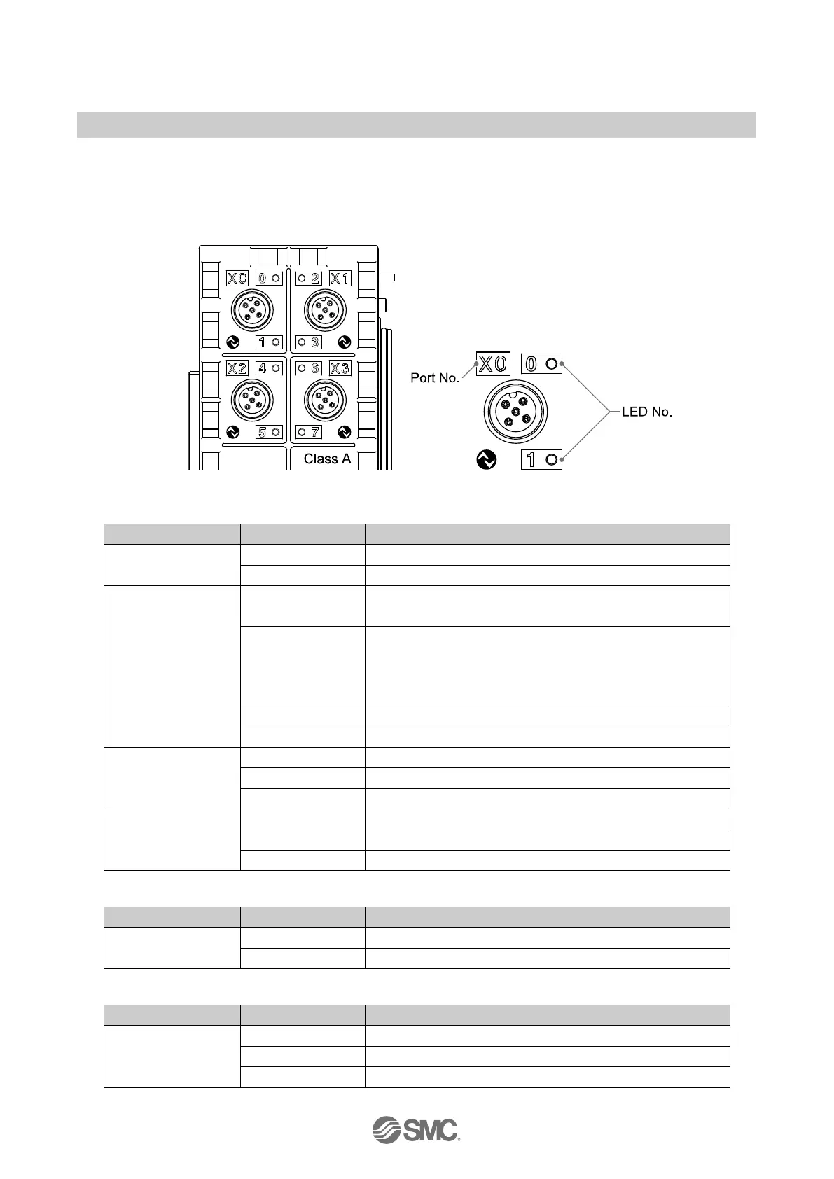
The status indicators are arranged on the EX245-LA1 / LB1 as shown in the illustration below.
The behaviour of the LEDs depends on the configured function and using module port class.
Table. 9-15 Status LED 0, 2, 4, 6 for Pin No. 4 C/Q
Port deactivated
Short circuit detection (L+)
IO-Link Device
Green flashing
(ON/OFF: 1 Hz)
IO-Link device disconnected
Green flashing
(ON/OFF: 2Hz)
One of the following error conditions has been detected:
•Connected IO-Link device matching error
•Data size error
•Data storage writing error
IO-Link device communicating
Short circuit (L+ or C/Q)
Digital input
OFF
Digital output
Short circuit (L+ or C/Q)
Table. 9-16 Status LED 1, 3, 5, 7, for Pin No. 2 I/Q (EX245-LA1, Port class A)
Digital input
(I/Q)
Table. 9-17 Status LED 1, 3, 5, 7, for Pin No. 2 P24 (EX245-LB1, Port class B)
Power supply
output (P24)
P24 Power supply for output ON
Red ON Short circuit (P24)
 Loading...